 Introduction:
When it comes to electrical circuits, understanding the behavior of components in different configurations is essential. One common arrangement is having a resistor and a capacitor placed in parallel. In this article, we will explore the relationship between a resistor and capacitor in parallel. We will discuss how they interact, the characteristics of their voltage and current, and how to calculate their combined impedance. By understanding the dynamics of this parallel configuration, you can effectively analyze and design circuits for various applications.
Introduction to Parallel Circuits
Parallel circuits occur when two or more components are connected across the same two points of a circuit.
A. Current Division: In a parallel circuit, the total current entering the junction splits into individual currents flowing through each branch.
B. Voltage Across Components: Components connected in parallel have the same voltage across them.
C. Component Independence: Each component in a parallel circuit operates independently of the others.
Resistor Behavior in Parallel
A resistor in parallel with other components affects the overall behavior of the circuit.
A. Current Division: In a parallel circuit, the current through each component is determined by Ohm’s Law (I = V/R), where V represents the voltage across the component and R is its resistance.
B. Impedance: The total impedance in a parallel circuit is inversely proportional to the sum of the reciprocals of each component’s resistance. The formula is given as 1/Z(total) = 1/R1 + 1/R2 + … + 1/Rn.
C. Voltage Across the Resistor: The voltage across each component in parallel is the same as the total voltage across the circuit.
 Capacitor Behavior in Parallel
A capacitor in parallel with other components exhibits specific characteristics.
A. Voltage Across the Capacitor: The voltage across each component in parallel is the same as the total voltage across the circuit, including the capacitor.
B. Current Division: In a parallel circuit, the current through each component is determined by the charge or discharge behavior of the capacitor and the impedance of the other components.
C. Impedance: The impedance of a capacitor in a parallel configuration is given as Z = 1/(jωC), where j represents the imaginary unit, ω is the angular frequency, and C represents the capacitance.
Behavior of Resistor and Capacitor in Parallel
The combination of a resistor and capacitor in parallel demonstrates specific behavior.
A. Voltage Division: The voltage across both the resistor and capacitor is the same and equal to the total voltage across the circuit.
B. Current Division: The current flowing through the resistor and capacitor branches depends on their respective impedances and the total current entering the parallel circuit.
C. Time Constant: The time constant of the parallel combination is determined by the product of the equivalent resistance (R) and the capacitance (C).
Analyzing Parallel Circuits: Example Calculation
To better understand the behavior of a resistor and capacitor in parallel, let’s analyze a simple example.
A. Given Values: Assume a 100Ω resistor and a 10μF capacitor are connected in parallel across a 12V power source.
B. Calculating Impedances: Calculate the impedance of the resistor (Z(R)) using its resistance value and the impedance of the capacitor (Z(C)) using the formula Z(C) = 1/(jωC).
C. Total Current and Current Division: Calculate the total current entering the parallel circuit using Ohm’s Law (I(total) = V/R(total)). Then, calculate the current flowing through the resistor (I(R)) and the capacitor (I(C)) using the impedance values.
D. Voltage Division: The voltage across both the resistor and capacitor is equal to the total voltage across the circuit, which is 12V in this case.
 Applications of Resistor and Capacitor in Parallel
Parallel combinations of resistors and capacitors have various applications in electronic circuits.
A. Filtering: Parallel combinations of resistors and capacitors are commonly used to create low-pass, high-pass, or band-pass filters in signal processing circuits.
B. Time Delay circuits: The combination of a resistor and capacitor in parallel can be used to create time delay circuits, such as in time delay relays or audio delay lines.
C. Equalizers: Parallel combinations of resistors and capacitors are often used in audio equalizer circuits to shape the frequency response.
The main difference between parallel resistance and series resistance:
The main difference between parallel resistance and series resistance lies in their connection methods and the overall effect on the total resistance of a circuit.
Parallel Resistance:
In a parallel circuit configuration, two or more resistors are connected side by side, with each end of the resistors connected to the corresponding ends of the other resistors. The main characteristic of parallel resistors is that the voltage across each resistor is the same, while the current flowing through each resistor may differ. When resistors are connected in parallel, the total resistance decreases compared to the resistance of any individual resistor. The formula to calculate the total resistance in a parallel circuit is:
1/R_total = 1/R1 + 1/R2 + 1/R3 + …
Series Resistance:
In a series circuit configuration, resistors are connected end-to-end, so that the current flowing through one resistor also flows through all the other resistors. The main characteristic of series resistors is that the total current flowing through the circuit is the same, while the voltage across each resistor may differ. When resistors are connected in series, the total resistance increases compared to the resistance of any individual resistor. The formula to calculate the total resistance in a series circuit is simply the sum of the individual resistances:
R_total = R1 + R2 + R3 + …
In summary, in a parallel configuration, the total resistance decreases because the current has multiple paths to follow, while in a series configuration, the total resistance increases because the current must pass through each resistor in sequence.
 To measure the resistance of parallel resistors:
To measure the resistance of parallel resistors, follow these steps:
Disconnect the power source: Before measuring the resistance, make sure the circuit is not powered. This ensures your safety and accurate readings.
Identify the parallel resistors: Determine which resistors are connected in parallel. In a parallel circuit, the resistors are connected side by side with each end of the resistors connected to the corresponding ends of the other resistors.
Disconnect the resistors: Temporarily disconnect the parallel resistors from the circuit by removing their connections. This isolates the resistors and allows for individual resistance measurement.
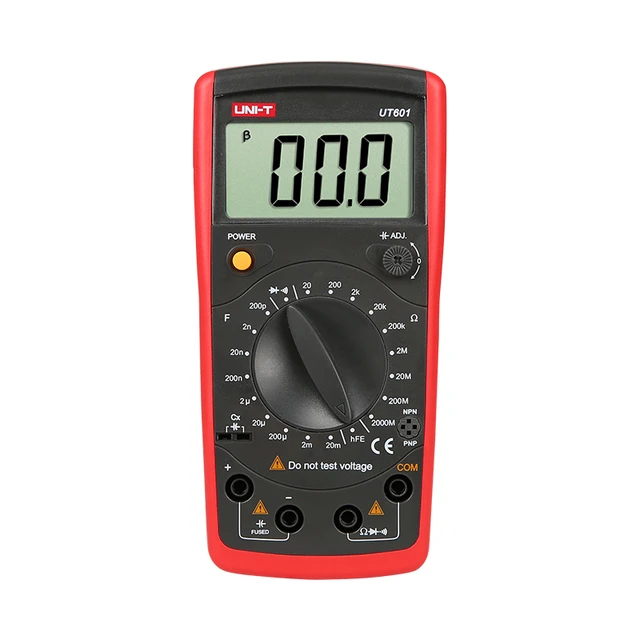
Select the resistance measurement mode: Set your digital multimeter to the resistance measurement mode (Ω) and choose an appropriate range. If you know the approximate resistance value, select the range accordingly for more accurate readings.
Measure resistance individually: Place the multimeter’s test leads on each end of an individual resistor and note the resistance reading on the multimeter display. Repeat this step for each resistor in the parallel configuration.
Calculate the total resistance: After obtaining the resistance readings for each resistor, calculate the total resistance of the parallel configuration using the formula:
1/R_total = 1/R1 + 1/R2 + 1/R3 + …
Take the reciprocal of each resistance value, sum them up, and then take the reciprocal of the sum to obtain the total resistance value.
It’s essential to ensure a proper connection and correct range selection on the multimeter for accurate resistance measurements. Additionally, double-check the results and reattach the resistors to the circuit after the measurements are complete.
 Conclusion
Understanding the behavior of a resistor and capacitor in parallel is fundamental to analyzing and designing electrical circuits. In a parallel configuration, the resistor and capacitor have independent effects on current division and voltage distribution. By understan