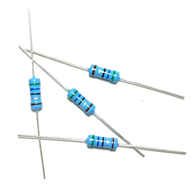
 Introduction of resistor in series:
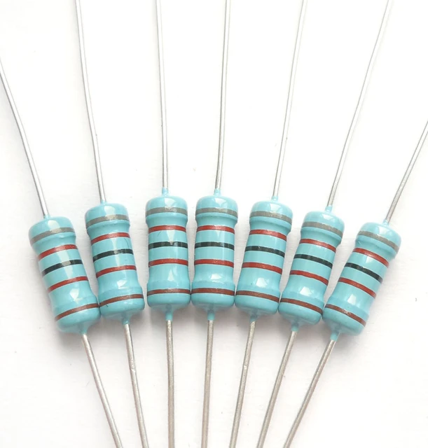
In electrical circuits, resistors are commonly connected in various configurations to achieve specific voltage drops, current divisions, or impedance matching. One such configuration is resistors connected in series. Understanding the behavior and characteristics of resistor in series is crucial for engineers and enthusiasts working with electronic circuits. In this comprehensive guide, we will explore the definition, properties, calculations, and practical considerations associated with resistors in series. By understanding these aspects, you can confidently analyze and design circuits using resistors connected in series.
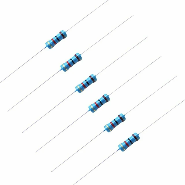 Definition and Properties of resistor in series
Definition:
Resistors in series refer to two or more resistors connected sequentially along the same current path, end to end.
In a series configuration, the same current flows through each resistor.
Total Resistance:
The total resistance in a series circuit is the sum of the individual resistances connected in series.
Total resistance (R_total) can be calculated as the algebraic sum of the resistances (R1, R2, R3, …) in the series: R_total = R1 + R2 + R3 + …
Current Flow:
In a series circuit, the same current (I) flows through each resistor.
The current is determined by the total resistance (R_total) and the applied voltage (V) using Ohm’s law: I = V / R_total.
Calculations and Analysis of resistor in series
Voltage Drop:
The voltage drop across each resistor in a series circuit is proportional to its resistance.
The voltage drop across each resistor (V1, V2, V3, …) can be calculated using Ohm’s law: V1 = I * R1, V2 = I * R2, V3 = I * R3, …
Power Dissipation:
The power dissipated by each resistor in a series circuit can be determined using Ohm’s law and the formula: P = I^2 * R, where P is the power and I is the current.
Current Division:
In a series circuit, the same current flows through each resistor, resulting in equal current distribution among resistors.
The current flowing through each resistor in a series circuit can be calculated using Ohm’s law and the formula: I = V / R_total.
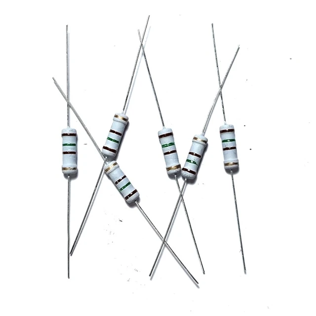 Practical Considerations for resistor in series
Power Ratings:
When connecting resistors in series, it is crucial to consider the power ratings of individual resistors.
Ensure that the power rating of each resistor is sufficient to handle the power dissipation based on the calculated voltage drops and current flow.
Tolerance and Precision:
Consider resistor tolerances and precision requirements for the application.
When connecting resistors in series, the overall tolerance of the combination can be calculated as the algebraic sum of tolerances.
Voltage Rating:
The voltage rating of each resistor should be greater than the maximum voltage drop across it.
Ensure that the selected resistor can withstand the applied voltage without breakdown or damage.
Practical Applications of Resistors in Series
Voltage Divider:
Resistors in series are commonly used in voltage divider circuits to obtain a desired output voltage from a higher input voltage.
The ratio of resistances determines the voltage division ratio.
Current Limitation:
By connecting a resistor in series, the current flowing through a specific component can be limited to protect it from excessive current.
This is commonly employed in LED circuits or protection circuits.
Sensing and Measurement:
Resistors in series are used as sensing elements, such as current sensing or voltage sensing.
By measuring the voltage drop across a resistor in series, various electrical parameters can be determined.
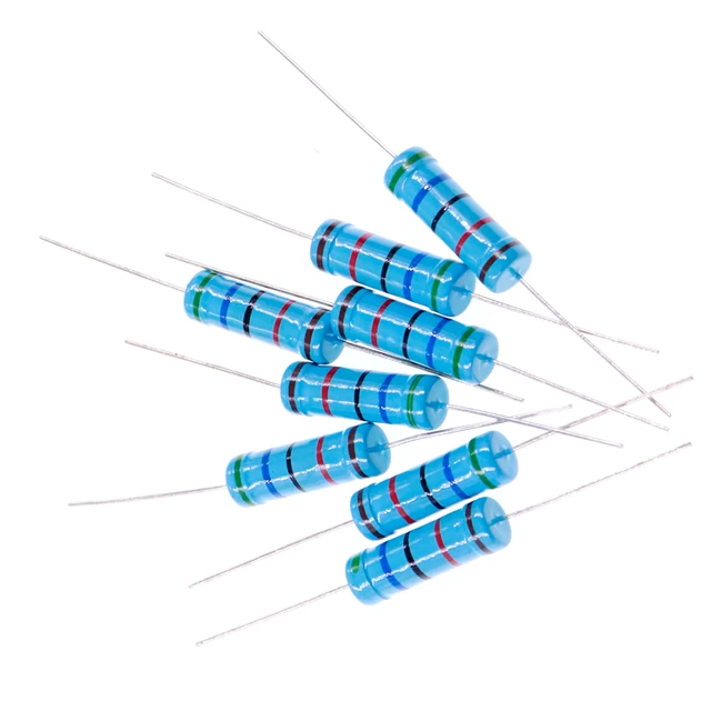 Comparison and distinction between series resistors, variable resistors, parallel resistors, and shunt resistors:
Here is a comparison and distinction between series resistors, variable resistors, parallel resistors, and shunt resistors:
Series Resistors:
Definition:
Series resistors are resistors that are connected in a series, one after the other, creating a single path for current flow.
Behavior:
In a series circuit, the current flowing through each resistor is the same, while the total resistance is the sum of all the individual resistances.
Purpose:
Series resistors can be used to create voltage dividers or divide the voltage across a circuit. They also increase the total resistance in a circuit and limit the current.
Variable Resistors:
Definition:
Variable resistors, also known as potentiometers or rheostats, are resistors with an adjustable resistance value. They have a moveable contact that allows the resistance to be changed.
Behavior:
The resistance of variable resistors can be varied by adjusting the position of the moveable contact, which changes the length of the resistive material through which the current flows.
Purpose:
Variable resistors are used to control the current or voltage in a circuit. They are commonly found in applications where adjustment or fine-tuning of resistance is required, such as volume controls, dimmer switches, or tuning circuits.
Parallel Resistors:
Definition:
Parallel resistors are resistors that are connected in parallel, providing multiple paths for current flow.
Behavior:
In a parallel circuit, the voltage across each resistor is the same, while the total resistance is related to the reciprocal sum of all the individual resistances.
Purpose:
Parallel resistors are primarily used to reduce the overall resistance in a circuit, allowing for the division of current and the distribution of power across multiple branches.
Shunt Resistors:
Definition: Shunt resistors, also known as current sense resistors, are resistors used to measure or redirect the current flow in a circuit.
Behavior:
Shunt resistors are typically placed in parallel with a component or circuit to divert a portion of the current through the resistor, allowing for measurement or providing a current path for monitoring or protection purposes.
Purpose:
Shunt resistors are commonly used in applications where current sensing is required, such as ammeters, circuit protection, or feedback in power electronics.
In summary, series resistors are connected in a chain, variable resistors allow for adjustable resistance, parallel resistors provide multiple current paths, and shunt resistors are used for current measurement or diversion. Each type serves distinct purposes in electrical circuits based on their connectivity, adjustability, or specific applications they are designed for.
 Conclusion of resistor in series:
Resistors in series offer practical applications and unique characteristics in electronic circuits. By understanding the definition, properties, calculations, and practical considerations outlined in this comprehensive guide, engineers and enthusiasts can confidently analyze and design circuits using resistors connected in series. Whether for voltage division, current limitation, or sensing applications, resistors in series serve crucial functions in modern electronic devices and systems. Let this guide serve as a valuable resource, enabling you to leverage the benefits and capabilities of resistors in series to enhance your circuit designs and optimize performance.
