How to Check Diode with Multimeter: A Comprehensive Guide
In the domain of electronics, the ability to diagnose and troubleshoot components effectively is critical. One essential component that frequently causes issues in electronic devices is the diode. A diode is a semiconductor device that allows current to flow in one direction only, playing a vital role in directing electrical flow and protecting sensitive components. Knowing how to check a diode with a multimeter is crucial for anyone working with electronics.
Testing diodes is often necessary during the repair and maintenance of devices. A multimeter is an invaluable tool that allows users to measure voltage, resistance, and current, making it suitable for checking many electronic components, including diodes. This comprehensive guide will provide you with detailed instructions on testing diodes, interpreting the multimeter readings, and troubleshooting various diode issues you might encounter.
By the end of this article, you will understand how to use a multimeter to check a diode’s functionality, recognize common diode problems, and adopt safe practices when performing these tests.
Understanding Diodes
What is a Diode?
A diode is a two-terminal semiconductor device that allows current to flow in one direction while blocking it in the opposite direction. This characteristic makes diodes essential for a wide variety of applications in electronic circuitry.
Diodes are often used for the following purposes:
– Rectification: Converting alternating current (AC) to direct current (DC). This is crucial in power supply applications that require steady voltage levels.
– Clamping: Limiting voltage levels to protect components from voltage spikes.
– Switching: Acting as electronic switches in certain types of circuits.
How Diodes Work
A diode consists of two layers of different semiconductor materials: the p-type and n-type. The junction formed between these two layers is called the p-n junction. The p-side of the diode has an abundance of holes (positive charge carriers), while the n-side has an abundance of electrons (negative charge carriers).
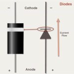
When a positive voltage is applied to the p-side (anode) concerning the n-side (cathode), the diode allows current to flow. This is known as forward bias. When a negative voltage is applied to the anode, it prevents current from flowing, which is known as reverse bias. This critical functionality makes diodes fundamental components in many electronic systems.
Types of Diodes
There are various types of diodes, each suited for specific applications. Some of the most common types include:
– Standard Diodes: Also known as rectifier diodes, they are used to convert AC to DC, commonly found in power supply circuits.
– Zener Diodes: Designed to allow reverse current flow when a specific voltage is reached, making them ideal for voltage regulation.
– Schottky Diodes: Known for their fast switching capabilities and low forward voltage drop, these diodes are commonly used in high-frequency applications.
– Light Emitting Diodes (LEDs): Diodes that emit light when an electric current passes through them, widely used in indicators and displays.
Understanding the specific type of diode you are working with is crucial when performing tests, as different diodes may exhibit unique characteristics.
Setting Up Your Multimeter for Diode Testing
Using a multimeter to check a diode requires specific settings to ensure accurate readings. Below are steps to set up your multimeter appropriately.
Selecting the Right Mode
1. Turn on Your Multimeter: Begin by ensuring your multimeter is powered on.
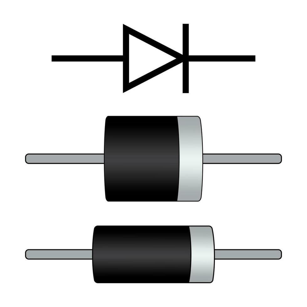
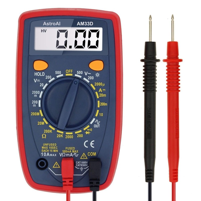
2. Choose Diode Test Mode: Most modern digital multimeters have a dedicated diode test setting. This mode is typically represented by a diode symbol (a triangle pointing into a line). If your multimeter doesn’t have a dedicated diode mode, you can also use the resistance (Ω) setting as an alternative, although it will be less effective for precise testing.
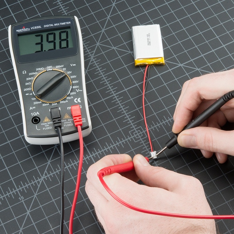
3. Connecting Probes: Insert the black probe into the COM (common) jack and the red probe into the VΩmA (voltage, resistance, and current) jack. Ensure that your probes are secure and in the correct ports.
Preparing the Multimeter for Accurate Readings
Before you begin testing, it’s essential to ensure that your multimeter is functioning correctly. Follow these steps:
1. Checking the Battery: Make sure the battery in your multimeter is fully charged. Low battery voltage can lead to incorrect readings.
2. Testing Probes for Continuity: Touch the two probes together to test for continuity. The multimeter should beep or provide a reading close to zero, indicating that the probes are working correctly. If there is no reading, check the probe connections.
3. Calibration: While most digital multimeters calibrate automatically, if you’re using an analog meter, make sure to calibrate it according to the manufacturer’s instructions before beginning your tests.
With your multimeter properly set up, you are now prepared to check the diode.
Step-by-Step Guide: How to Check a Diode with a Multimeter
Now that your multimeter is ready, you can follow these steps to effectively check a diode’s functionality.
Step 1: Disconnect Power
Before starting the testing process, ensure that the circuit containing the diode is powered off. This prevents any risk of electric shock or damage to the multimeter. If the diode is part of a larger circuit, it’s a good idea to remove the diode from the circuit to get a more accurate reading.
Step 2: Identify the Diode’s Terminals
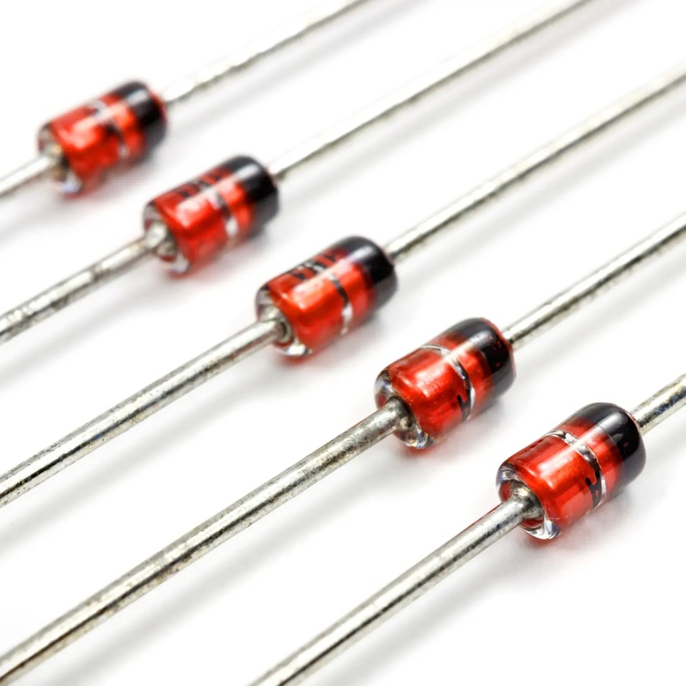
Before proceeding, it’s essential to know which terminal of the diode is the anode and which is the cathode. The anode is typically marked with a positive symbol (+) or is the unmarked side, while the cathode often has a stripe or band on the negative end (-).
Step 3: Test Forward Bias
1. Connect the Probes: Start by connecting the red probe to the anode and the black probe to the cathode of the diode.
2. Read the Display: A functioning diode should display a forward voltage drop between 0.6V and 0.7V for silicon diodes. For germanium diodes, the reading may range between 0.2V and 0.3V. Any reading in this range indicates that the diode is working properly.
Step 4: Test Reverse Bias
1. Reverse the Probes: Next, reverse the probe connections by placing the black probe on the anode and the red probe on the cathode.
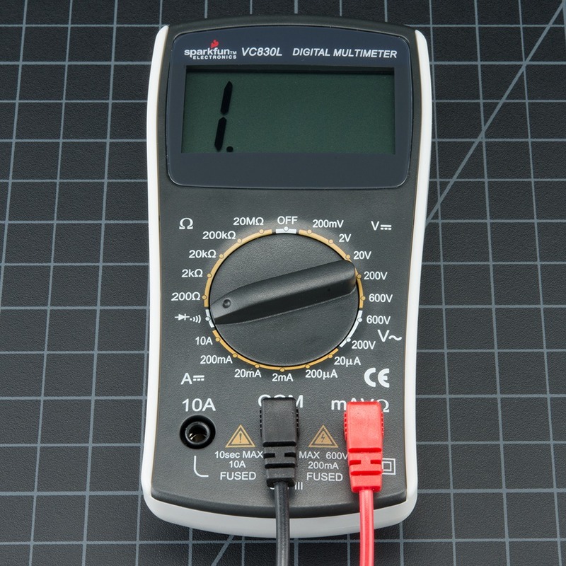
2. Read the Display Again: In this configuration, a healthy diode should display no reading or infinite resistance, typically indicated as “OL” on digital multimeters. This indicates that the diode is effectively blocking reverse current, which is its intended function.
Step 5: Document Your Findings
Once you complete the tests, take note of your findings. Write down the readings for future reference, especially if you suspect a malfunction in the circuit. If you encounter a reading outside the expected ranges, further investigation may be warranted.
Safety Precautions
While testing diodes, always ensure safety remains a priority. Here are some precautions:
– Wear Protective Gear: Consider wearing gloves and eye protection when handling electronic components.
– Avoid Contact with Live Circuits: Never attempt to measure diodes while circuits are energized.
– Handle Components Carefully: Avoid placing excessive pressure on the diode or multimeter probes during testing.
Interpreting Multimeter Readings
Understanding how to interpret your multimeter readings is crucial for diagnosing diode functionality. Here’s how to make sense of the outcomes.
Forward Bias Readings
– Good Diode: If you receive a reading between 0.6V and 0.7V for silicon diodes, this indicates that the diode is functioning correctly.
– Suspicious Readings: A reading of 0V signifies a shorted diode, while infinite resistance suggests an open diode. Such readings suggest a failed component that should be replaced.
Reverse Bias Readings
– Good Diode: A reading of “OL” indicates that the diode is working correctly by blocking reverse current.
– Bad Diode: If you receive a finite reading during reverse testing, this indicates that the diode has failed and allows current to flow in reverse, compromising the circuit’s integrity.
Common Diode Issues and Troubleshooting
Even with careful testing, diodes can occasionally fail. Understanding common issues can help you troubleshoot effectively.
Typical Diode Problems
1. Shorted Diodes: This can occur due to excessive voltage or overheating. Symptoms of a shorted diode often include a reading of 0V in both forward and reverse bias tests. If a diode is shorted, it needs to be replaced immediately.
2. Open Diodes: An open diode will typically show an infinite reading for both testing conditions. This can occur due to physical damage or defects in manufacturing. If you have an open diode, it is essential to replace it.
3. Leakage Issues: Some diodes may still allow a small amount of current to leak in reverse, indicating they may be failing. If the reverse bias reading is significantly lower than expected but still not zero, consider replacing the diode.
Diagnosing and Resolving Issues
– Confirm Proper Orientation: Ensure that you are testing the diode in the correct orientation. If readings are inconsistent, double-check your probe connections.
– Inspect Related Components: If the diode tests faulty, inspecting associated circuitry for damage is prudent, as components may interact in ways that lead to diode failures.
– Replacement: Determine the specifications (voltage and current ratings) of the diode before replacing it. Ensure that the new diode matches the original component’s specifications.
– Re-Testing: Always re-test after replacing the diode to verify proper functionality.
Conclusion
Knowing how to check a diode with a multimeter is an essential skill for anyone working in electronics. With the right tools and techniques, you can effectively diagnose and repair circuits quickly, saving time and resources.
Throughout this guide, we have covered the importance of diodes, the necessary multimeter setup for testing, and the step-by-step procedure to check their functionality. We’ve also discussed how to interpret your multimeter readings and troubleshoot common issues that arise with diodes.
As you gain confidence in this skill, consider expanding your knowledge to additional electronic components and testing methods. Continual practice will not only enhance your technical aptitude but also empower you to tackle larger and more complex projects confidently.
Whether you are an industry professional, a student, or simply a hobbyist, mastering diode testing will enhance your capabilities in the field of electronics. Embrace the learning journey and happy testing!

