Introduction
Testing diodes accurately is crucial for maintaining healthy electronic systems. Diodes, small yet vital components in various circuits, control the direction of current flow. Ensuring they function correctly prevents potential system failures and malfunctions. This guide provides detailed steps on how to test a diode using a multimeter, which is a versatile tool in electronic diagnostics.
Importance of Testing Diodes
Regular diode testing helps in early detection of issues and extends the lifespan of electronic devices. It ensures that diodes perform their role of allowing current to pass in a single direction, protecting circuits by blocking reverse currents. This testing is essential before incorporating diodes into any electrical circuit to prevent damage and ensure efficiency.
Types of Diodes and Their Applications
Understanding the various types of diodes and their specific applications is key for effective testing and usage.
Common Diodes and Their Uses
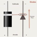
Diodes serve as crucial components in countless electronic devices. They control the flow of electricity making them indispensable in circuits. Common diodes found in electronic systems include standard rectifier diodes, which are used primarily for converting alternating current (AC) into direct current (DC). Another frequently used type is the Schottky diode, known for its low forward voltage drop and high-speed switching capabilities, making them ideal for high-frequency applications. In a diode, the cathode and anode play vital roles in directing the flow of electricity, ensuring efficient circuit functionality.
Zener and LED Diodes Specifics
Zener diodes and Light Emitting Diodes (LEDs) have more specialized uses. But zener diodes are widely utilized for voltage regulation, protecting circuits by allowing current to flow backwards when a specified voltage threshold is exceeded. LEDs, on the other hand, are primarily used for lighting and display purposes due to their efficiency and the variety of colors they emit. Testing these diodes requires understanding their unique characteristics to ensure they function as expected in their specific roles. To properly test Zener diodes and LEDs, use the diode setting on a multimeter to ensure they operate as intended in their specialized roles.
Setting Up Your Multimeter for Diode Testing
To start testing diodes, you need to set up your multimeter correctly. This step is crucial for accurate results.
Understanding Multimeter Settings
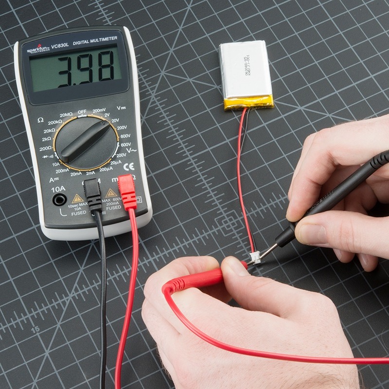
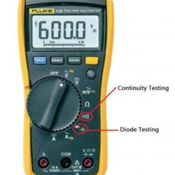
First, you should get familiar with the multimeter’s settings. Multimeters can measure voltage, current, and resistance, but for diodes, you need a special setting. Look for the diode symbol or the continuity setting. It usually shares a spot on the dial with resistance.
Identifying Diode Test Mode
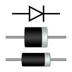
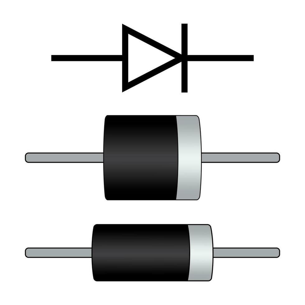
Next, find the Diode Test Mode on your multimeter. This mode provides the correct voltage for testing diodes. It typically shows an icon that looks like a triangle pointing to a line. Turn the dial to this option to begin testing your diodes accurately.
Testing Procedure for Standard Diodes
To ensure your diode is working correctly, follow a standard procedure using your multimeter. Testing involves forward and reverse bias tests to check the diode’s function in each direction.
Forward Bias Test
Start by setting your multimeter to Diode Test Mode. This mode is ideal for testing diode function. Identify the anode and cathode of your diode. Connect the multimeter’s positive lead to the anode and the negative to the cathode. This sets up the diode in forward bias and prepares it for testing.
Observe the multimeter’s reading. A typical forward-biased silicon diode should show a voltage drop between 0.5 to 0.8 volts. This indicates a good diode allowing current to pass through. If the reading is significantly higher or lower, your diode may be defective.
Reverse Bias Test
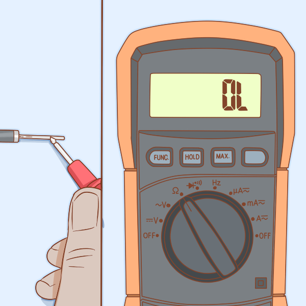
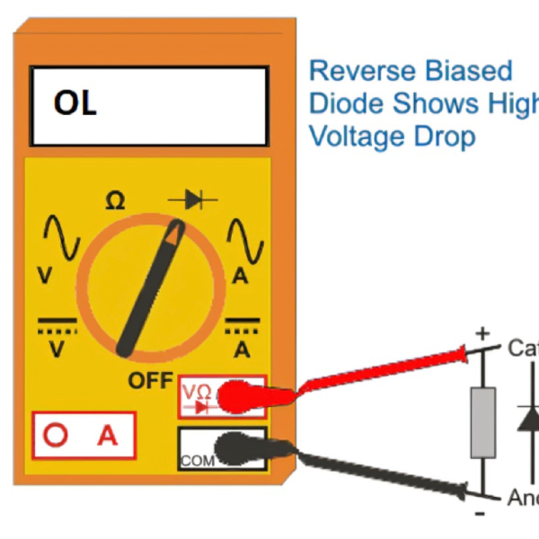
After testing in forward bias, reverse the leads. Place the positive lead on the cathode and the negative on the anode. The multimeter should now read ‘OL’ or a very high resistance value. This confirms the diode blocks current flow in reverse bias as it should.
If the reverse bias test shows voltage drop similar to the forward bias, the diode is likely faulty. It may be allowing current in both directions when it should not.
Interpreting the Results
A working diode will have a low-voltage drop in forward bias and high resistance or ‘OL’ in reverse bias. If your diode does not follow this pattern, it may be time to replace it.
Make sure to conduct these tests on a diode that is out of the circuit. Other components may affect your readings, leading to incorrect conclusions. Also, compare readings with a known good diode for more accurate results.
Testing Procedure for Special Diodes
To ensure that your electronic project works as expected, the testing of special diodes such as Zener diodes and LEDs is a crucial step.
How to Test Zener Diodes
Zener diodes are primarily used for voltage regulation in circuits. Testing these diodes involves verifying that they can conduct in reverse-bias above a certain voltage threshold, known as the Zener voltage.
- Identify the Diode Terminals: Begin by identifying the anode and cathode, typically marked on the diode body.
- Set Up the Multimeter: Set your multimeter to voltage measuring mode. Prepare the test circuit by connecting a suitable resistor in series with the diode.
- Conduct the Test: Connect the multimeter probes across the diode, with the multimeter set to measure DC voltage. Gradually increase the supply voltage until the Zener voltage is reached. Observe if the voltage across the diode stabilizes at the Zener voltage as expected.
- Analyze the Results: If the diode maintains a constant voltage equal to the Zener voltage despite increases in the input, the diode is functioning correctly. If the voltage fluctuates or does not reach the expected value, the diode may be defective.
How to Test Light Emitting Diodes (LEDs)
LEDs are used in various applications for their efficient light output. Testing them ensures that they illuminate correctly and can be a simple process as follows:
- Identify the LED Terminals: Determine the anode and cathode, using lead length or the flat side to identify the cathode.
- Prepare the Multimeter: Place your multimeter in diode mode, which typically supplies a small current suitable to test LEDs.
- Perform Forward Bias Test: Connect the multimeter’s positive lead to the anode and the negative to the cathode. The LED should light up if it is working.
- Result Interpretation: If the LED lights up and displays a forward voltage drop typically around 1.5-3 volts depending on the LED type, it is functioning properly. No light or abnormal voltage suggests a defective LED.
For both diode tests, ensure the power supply is isolated, and the circuit is not live to prevent any short circuits or damage to the diodes.
Troubleshooting Diode Test Results
When your diode test results don’t match the expected outcome, it’s essential to troubleshoot. Here’s what to do if your diode test fails and some tips for effective diode testing.
What to Do If Diode Test Fails
If the forward bias test shows a high voltage or the reverse bias test doesn’t show high resistance, your diode might be faulty. First, double-check for any setup errors. Ensure the multimeter is in the correct setting and leads are properly connected. If the setup is correct, but the diode still fails tests, it likely needs replacement. Understanding the diode purpose is essential, as a faulty diode can disrupt circuit functionality and lead to incorrect measurements during testing.
Check the diode for any physical damage such as cracked casing or burnt marks. If you find damage, replace the diode. If there’s no visible damage, test the diode in a known working circuit or compare it with a new one.
Tips for Effective Diode Testing
To get reliable results, follow these tips when testing diodes with a multimeter:
- Ensure the multimeter is calibrated for accuracy.
- Disconnect the diode from the circuit for isolated testing.
- Use fresh batteries in the multimeter to maintain correct voltage for testing.
- Clear the area of any potential electrical interference.
- Familiarize yourself with the multimeter manual to use it effectively.
By following these steps, you’ll improve your chances of an accurate diagnosis and prevent further damage to the circuit.
Safeguards and Precautions
Proper care is vital when testing diodes with a multimeter. This section outlines safety measures and tips for ensuring accurate testing results.
Safety Measures While Testing
While testing diodes, prioritize your safety and the integrity of the components.
- Turn Off Power: Always ensure the power supply to the circuit is off to avoid electric shock.
- Use Correct Setting: Set your multimeter to the appropriate mode to prevent damage to the device.
- Handle with Care: Physically inspect diodes for damage before testing to prevent injury or further damage.
- Discharge Capacitors: Discharge all capacitors in the circuit to avoid residual voltage that can cause harm or false readings.
- Isolate Diode: When possible, remove the diode from the circuit for precise testing.
By following these safety steps, you minimize risks associated with diode testing using a multimeter.
Ensuring Accurate Diode Testing
For reliable diode test results, accuracy is key. Here are tips to ensure your tests are correct:
- Calibrate Multimeter: Regularly calibrate your multimeter for precise measurements.
- Check Battery: Make sure the multimeter’s battery is fully charged for consistent performance.
- Use Known Good Diode: Compare your results with a known functional diode for reference.
- Follow Manufacturer’s Guidelines: Always refer to the diode’s datasheet for specific testing parameters.
- Confirm Lead Connection: Double-check that your leads are properly connected and in good condition.
Applying these measures improves the accuracy of your diode tests and secures trustworthy results. Testing diodes carefully and methodically contributes to the optimal performance of electronic devices.


