Introduction to Diode Testing
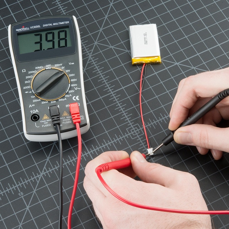
Testing diodes is a key step in electronic troubleshooting and maintenance. By using a digital multimeter, you can determine if a diode is functioning correctly. A proper test reveals whether a diode allows current to flow in one direction, as it should. Two methods exist for testing diodes with a digital multimeter: Diode Test mode and Resistance mode. In Diode Test mode, the multimeter sends a small current through the diode, measuring the voltage drop.
A functioning diode will show a voltage drop indicative of its type, like silicon or germanium. In Resistance mode, the multimeter measures the diode’s resistance in both forward and reverse biases. This mode is useful when Diode Test mode is not available, but it provides less definitive results. When testing, ensure the diode is disconnected from any power source. Also, remember that a diode in a circuit may give false readings, so it might be necessary to remove it for accurate testing. Understanding diode test results is critical for any electronic diagnostic work. The following sections of this blog will guide you through using both test modes effectively. We will explain how to interpret the results and troubleshoot effectively with your digital multimeter.
Essentials of the Diode Test Mode
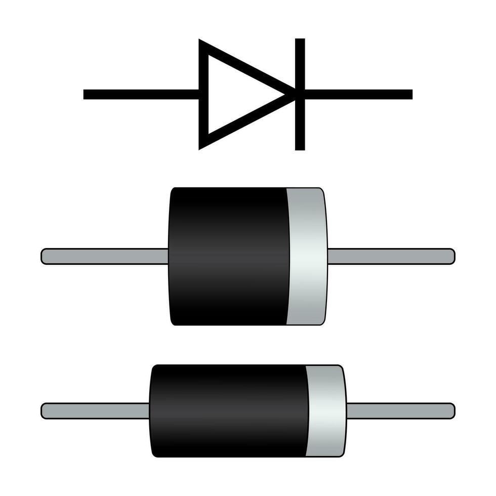
Understanding the essentials of the Diode Test Mode is crucial for any technician or hobbyist looking to effectively use their digital multimeter for diode testing. This mode is specifically designed to test the functionality of diodes, which are semiconductor devices allowing current to flow in one direction. Diode Test Mode operates differently than the other functions on a digital multimeter by applying a small voltage across the diode and measuring the voltage drop that occurs as a result. When performing microwave diode replacement, understanding the Diode Test Mode of your digital multimeter is essential, as it ensures accurate testing of diode functionality by measuring the voltage drop across the component.
When using the Diode Test Mode, a digital multimeter typically sends a current of approximately 1 to 2 milliamps through the diode. The reading on the multimeter will show the voltage drop across the diode when it is forward-biased. A good silicon diode should have a forward voltage drop between 0.5 to 0.8 volts, while a germanium diode will usually read between 0.2 to 0.3 volts. These readings confirm the diode’s capability to permit current in one direction.
In reverse bias, where the diode should not conduct, the multimeter should display ‘OL’ or a very high resistance value, indicating that no current is passing through the diode in the reverse direction. This suggests that the diode is functioning properly as an electrical check valve. It is important to note that these readings are typical for silicon and germanium diodes, and different types of diodes may have varying voltage drop values.
Moreover, to achieve accurate readings, it is imperative that the diode is disconnected from any power source and removed from the circuit when possible. This helps in avoiding erroneous readings that can be caused by other components in the circuit. As part of best practices, always ensure your multimeter’s battery is in good condition to prevent inaccurate readings due to low battery voltage.
By mastering the Diode Test Mode, you’ll be able to quickly ascertain the health of a diode and effectively diagnose potential issues in electronic circuits.
Step-by-Step Diode Test Procedure
Conducting a systematic diode test with a digital multimeter is straightforward. Follow these steps for reliable results:
- Power Off the Circuit: Ensure the circuit is not energized. This prevents damage to both the diode and the multimeter.
- Detach the Diode: If possible, remove the diode from the circuit. This yields the most accurate readings by eliminating potential interference from other components.
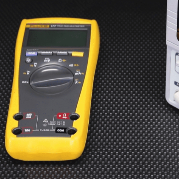
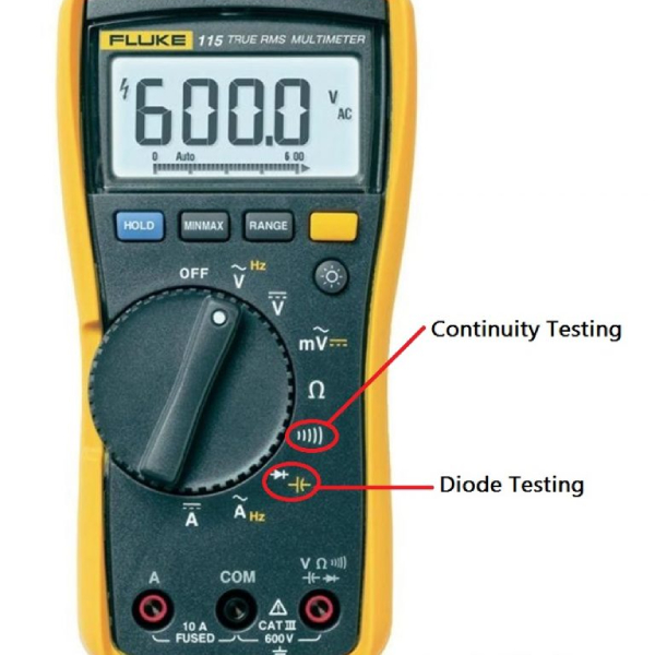
- Set the Multimeter: Adjust your digital multimeter to the Diode Test mode. This function is usually indicated by a diode symbol on the dial.
- Connect the Leads: Attach the red test lead to the diode’s anode and the black lead to the cathode.
- Record the Forward Bias Reading: Note the voltage displayed by the multimeter. A typical silicon diode should exhibit a voltage drop between 0.5 and 0.8 volts.
- Test for Reverse Bias: Swap the test leads to reverse the bias. The multimeter should reflect ‘OL’ or high resistance, suggesting no current flow in reverse.
These steps form the core of the Diode Test Procedure with your digital multimeter. Performing them correctly ensures the diode’s functionality is accurately assessed.
Understanding the Resistance Mode in Diode Testing
While the Diode Test mode is ideal, not all digital multimeters come with this feature. In such situations, Resistance mode steps in as a valid alternative for diode testing. This method lacks the specificity of the Diode Test mode but can still provide useful information about a diode’s health. Resistance mode operates by measuring the ohmic value across the diode in both forward and reverse bias. Here’s how to utilize this mode effectively:
- Prepare the Diode: Confirm the diode is power-free and disconnect it from the circuit when feasible.
- Set to Resistance Mode: Turn your multimeter’s dial to the position marked by the resistance symbol or “ohm”.
- Connect Multimeter Leads: Touch the red lead to the anode and the black to the cathode for a forward-biased reading.
- Record Forward Resistance: A functioning diode will show low resistance in forward bias, though not as low as when using Diode Test mode.
- Reverse Leads for Reverse Bias: Swap the leads and measure again. A good diode will give a high resistance reading or show ‘OL’.
Remember, results in Resistance mode can be misleading if the diode remains in the circuit due to parallel paths that can affect the reading. Comparing resistance readings with those of a known good diode can aid in interpretation. When using Resistance mode, be conscious of the multimeter’s limitations and recognize that some uncertain or borderline readings might require further investigation with more specialized equipment or methods.
Resistance mode is a good initial check that can quickly identify a completely failed diode but may not be as clear-cut for one that is failing. Always cross-reference your findings with the diode’s datasheet and, if possible, confirm with Diode Test mode or other testing techniques. When evaluating diode functionality, especially using a tool like the Diode Dynamics SS3 Pro, it’s essential to consider how parallel paths can skew resistance readings, necessitating cross-references with datasheets and potentially using Diode Test mode for accurate assessments.
How to Interpret Diode Test Results
Interpreting the results from diode testing with a digital multimeter is essential to confirm a diode’s functionality. Accurate interpretation leads to effective diagnostics and repair. Here’s how you can understand the results you’ve gathered from both the Diode Test Mode and Resistance Mode:
Forward Bias Test Results Interpretation
In Forward Bias, when using the Diode Test Mode, a properly functioning silicon diode will display a voltage drop between 0.5 and 0.8 volts. For germanium diodes, expect a reading of 0.2 to 0.3 volts. If the readings are within these ranges, the diode likely operates correctly, allowing current flow in one direction.
Reverse Bias Test Results Interpretation
In Reverse Bias, a good diode will not conduct. Your multimeter should show ‘OL’ or a very high resistance value. This result confirms the diode is blocking current as it should in the reverse direction.
Resistance Mode Results Interpretation
When using Resistance Mode for diode testing, a low resistance in forward bias suggests the diode is healthy. Conversely, a high resistance or ‘OL’ in reverse bias indicates proper function. However, readings in this mode are less specific and can vary greatly.
Keep in mind the specific characteristics of the diode being tested, as they can affect the expected results. Always compare your readings with the manufacturer’s specifications for the most accurate interpretation. Consistent results across multiple tests will also help confirm the health of the diode. When assessing diode resistance, it is crucial to understand the unique properties of the diode and compare your measurements with the manufacturer’s guidelines, as this will ensure accurate results and confirm the diode’s functionality through consistent testing outcomes.
Troubleshooting with Resistance Mode Measurements
When using a digital multimeter in Resistance Mode for diode testing, you embark on a troubleshoot that, while less specific than Diode Test Mode, can still be quite revealing. Below are steps and tips for effective troubleshooting using this method:
- Ensure Safety: Disconnect the diode from its power source to prevent damage to the multimeter.
- Isolate the Diode: Remove the diode from the circuit if you can. This gives a clear picture of its condition.
- Select Resistance Mode: Turn your multimeter’s dial to the resistance or ‘ohm’ setting.
- Test for Forward Bias: Connect the leads with red to the anode and black to the cathode. A lower resistance value suggests the diode is functioning in this bias.
- Switch for Reverse Bias: Flip the leads and check resistance again. A high resistance or ‘OL’ reading indicates no current flow in reverse, as expected for a working diode.
When the diode does show unexpected resistance values, consider comparing it to a new diode. Such a comparison can help ascertain whether the diode under test has gone bad. Consistent and unusual readings might also hint at potential issues that call for more in-depth analysis with additional tools or testing procedures. Always follow best practices and cross-check your findings with the manufacturer’s specifications. Proper interpretation of resistance readings helps to ensure that you troubleshoot efficiently and accurately identify diode health.
Best Practices for Accurate Diode Testing
To get the most accurate results when testing diodes with a digital multimeter, follow these best practices:
- Verify Multimeter Functionality: Before starting, make sure the multimeter is working properly. Test it on a known working diode or check its battery level.
- Discharge Capacitors: Capacitors in the circuit can hold charge. Always discharge them to avoid false readings or damage.
- Remove the Diode from the Circuit: If possible, test the diode outside of the circuit for isolation from other components.
- Avoid Physical Damage: Handle the diode carefully. Physical damage can impact the accuracy of your test results.
- Follow Manufacturer Specifications: Check the datasheet for the ideal test conditions and compare your results with the specified values.
- Use Correct Test Mode: Utilize Diode Test mode over Resistance mode if available, for better accuracy.
- Repeat Tests: To ensure reliability, repeat the test multiple times. Consistent results are a good indicator of diode health.
- Document Results: Keep records of your results for future reference, which can aid in ongoing maintenance.
- Perform Comparative Tests: If uncertain, compare readings with those from a new diode to help identify any discrepancies.
By adhering to these practices, you can minimize errors and ensure accurate diode testing with your digital multimeter.
Common Errors and How to Avoid Them
When testing diodes with a digital multimeter, errors can sometimes occur. These errors can lead to incorrect diagnosis of diode health. To avoid common mistakes, consider the following tips:
- Check Multimeter Calibration: Ensure your multimeter is calibrated correctly. An uncalibrated multimeter can give inaccurate readings.
- Observing Polarity: Always connect the red lead to the anode and the black lead to the cathode. Reversing leads can cause confusion.
- Battery Level: A low battery in your multimeter may result in inaccurate measurements. Replace batteries regularly.
- Incorrect Mode: Make sure you are using the Diode Test mode if your multimeter has one. Using the wrong mode can lead to improper readings.
- Test Lead Condition: Damaged or poor-quality test leads can compromise test results. Inspect and replace them if necessary.
- Environmental Factors: Temperature and humidity can affect diode performance. Test diodes in a controlled environment if possible.
- Component Interference: Other components in the circuit can interfere with diode readings. Isolate the diode from the circuit if you can.
- Repeated Testing: Perform multiple tests to confirm your findings. One-off readings may be flukes.
- Documentation Comparison: Always compare your test results with the specifications provided by the diode’s manufacturer.
By being mindful of these potential errors and how to avoid them, you can perform more accurate and reliable diode testing using your digital multimeter.