Introduction to Zener Diodes
Zener diodes stand out in the electronics world. These components conduct current in both directions. Unlike regular diodes, Zener diodes are made to handle reverse voltage. They are valuable in various applications. You’ll find Zener diodes across many circuits, safeguarding against voltage spikes. They work by allowing current to flow, once a specific voltage is reached. This unique feature is what defines them. They’re named after physicist Clarence Zener. He uncovered the Zener effect, vital for these diodes. Understanding how a Zener diode works is crucial for many electronic designs. They’re not just for academics but have real-world uses in devices we use every day.
Essential Principles of Zener Diode Operation
Understanding how Zener diodes operate involves a grasp of several key concepts. These diodes differ fundamentally from regular diodes due to their ability to conduct in reverse bias. They have a specific voltage, known as the Zener voltage, at which this reverse conduction occurs. Below are the essential principles that underlie Zener diode operation:
- Reverse Bias Activation: Unlike conventional diodes that block current in reverse bias, Zener diodes allow current to flow when the reverse voltage exceeds a certain threshold – the Zener voltage (Vz).
- Controlled Breakdown: A Zener diode is designed to undergo controlled electrical breakdown at the Zener voltage, enabling it to conduct in reverse without damage.
- Voltage Regulation: One of the primary functions of a Zener diode is to maintain a stable voltage across a load, making it a critical component in power supply circuits.
- Wide Range of Zener Voltages: Zener diodes are available with a variety of breakdown voltages, allowing for their use in different applications based on the voltage requirements.
These principles come together to make Zener diodes invaluable in circuits that require voltage stabilization and protection from voltage spikes. Recognizing these principles helps in more comprehensively understanding the performance and functionalities of Zener diodes. Flywheel diodes, like Zener diodes, are essential for managing voltage spikes in circuits. Both components ensure stability and protect sensitive equipment from overloads.
Understanding Reverse Bias in Zener Diodes
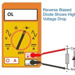
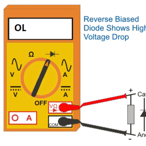
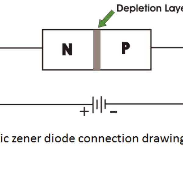
In simple terms, reverse bias in Zener diodes unlocks their unique abilities. When connected in reverse, with the anode to negative and the cathode to positive, they block current like typical diodes until the Zener voltage is reached. Upon reaching this critical voltage, the diode’s behavior changes dramatically.
Here’s what happens when a Zener diode is reverse biased:
- Initial Blockade: Initially, the Zener diode prevents current from flowing backwards, safeguarding circuit components.
- Zener Voltage Achievement: As reverse voltage rises and hits the Zener voltage, a significant event occurs. The diode starts to conduct.
- Regulated Conduction: After the onset of conduction, the Zener diode allows current to pass in reverse, but in a controlled manner.
The critical factor is the Zener voltage which is a precise value characteristic to each Zener diode. Manufacturers design these diodes to have Zener voltages suitable for different tasks. The ability to handle reverse bias is what makes Zener diodes so useful in circuits. They are like guards that step aside at the right moment, permitting controlled flow to protect electronic components from harm.
Breakdown Mechanisms Explained
In any discussion about how a Zener diode works, it’s important to understand the breakdown mechanisms that enable its functionality. These breakdown mechanisms are the heart of a Zener diode’s ability to regulate voltage and protect circuits from overvoltage.
Avalanche Breakdown
Avalanche breakdown occurs when the reverse voltage applied to a diode gets extremely high. At this point, free electrons accelerate and smash into atoms with enough force to knock off more electrons. This creates a chain reaction, rapidly increasing the flow of electric current. In Zener diodes, the design ensures that they can handle this sudden increase without being damaged. During an alternator diode test, it’s crucial to monitor reverse voltage levels to prevent avalanche breakdown and ensure optimal functionality of the diodes.
Zener Breakdown
Zener breakdown happens at a lower voltage than avalanche breakdown. In this scenario, a strong electric field pulls electrons away from their atoms. With enough voltage, these electrons can escape and contribute to current flow. This is a direct result of the Zener effect. Zener diodes are purposely built to safely operate when this effect takes place, stabilizing the voltage to the expected Zener voltage. A diode array can effectively utilize Zener diodes to regulate voltage by leveraging the Zener effect. This enables reliable and stable performance in electronic circuits.
Considering these mechanisms helps us see how Zener diodes can act as robust voltage regulators in numerous electronic circuits. Each type of breakdown has its place in ensuring Zener diodes do their job effectively.
Comparing Avalanche
Zener diodes exhibit two types of breakdowns—Avalanche and Zener—each with its unique mechanism. Let’s compare these breakdowns to better understand how a Zener diode works.
Avalanche Breakdown
Avalanche breakdown is an effect seen in Zener diodes with higher Zener voltages, typically above 6V. Here, the reverse voltage becomes so high that free electrons gain massive energy. They collide with atoms, releasing more electrons. This chain reaction leads to an increase in current. Although similar events can destroy normal diodes, Zener diodes withstand this without damage.
Zener Breakdown
Zener breakdown, meanwhile, occurs at lower voltages, beneath 5.6 volts. It’s a quantum mechanical process where a strong electric field inside the diode frees electrons. This leads to a quick spike in the electric current. Zener diodes are designed to operate safely under Zener breakdown, maintaining a constant voltage through this effect.
By considering these differences, we can appreciate the sophisticated design of Zener diodes. They can regulate voltage and protect against overvoltage, ensuring stability and safety in electronic circuits. With these mechanisms in play, Zener diodes become crucial for more efficient and resilient electronic design.
Zener Diode Circuit Symbols and Packaging
Zener diodes have unique symbols and packaging types that set them apart in electronic schematics and components. They are commonly illustrated in circuit diagrams to show their distinct behavior compared to standard diodes. Understanding these symbols and packaging can help in identifying and utilizing Zener diodes properly.
Recognizing the Circuit Symbol
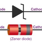
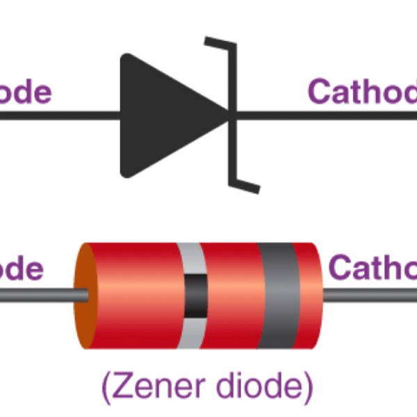
The Zener diode symbol looks like the standard diode icon but with additional elements. It contains a triangle pointing at a vertical line, paired with two small horizontal lines on the cathode side. These horizontal lines signal the diode’s ability to conduct in reverse once the Zener voltage is exceeded.
Various Packaging Options
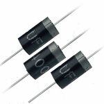
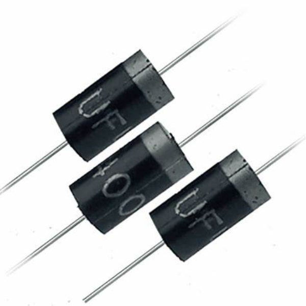
Zener diodes come in several forms to suit different power needs. They are found in glass or plastic packages and vary from small signal diodes to power diodes. Some are designed for surface mounting and others for through-hole fitting. The cathode is often marked with a band for easy recognition.
High-power versions are available for heavy-duty use. Surface mount Zener diodes cater to modern circuit board design. Their varied packaging ensures they fit into numerous applications, from tiny mobile devices to large industrial machines.
When selecting a Zener diode, consider both symbol and packaging. They tell us much about how the diode works and where it can be best applied. This knowledge is essential for circuit design and choosing the right component for voltage regulation and protection tasks.
V-I Characteristics Analysis
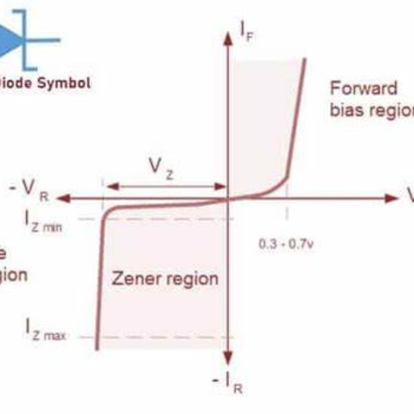
The V-I characteristics of a Zener diode display its behavior under various voltage conditions and are crucial for understanding how Zener diodes work within electronic circuits.
Forward V-I Characteristics
In the forward direction, Zener diodes operate like typical diodes. This is evident in the forward V-I characteristics, where current increases gradually as voltage rises, before the threshold where it sharply increases at the turn-on voltage. This part of the V-I curve resembles that of standard diodes, indicating diode’s conductivity once the forward voltage exceeds the junction threshold.
Reverse V-I Characteristics
The reverse bias V-I characteristics are what set Zener diodes apart. Initially, as reverse voltage is applied, there’s a minute leakage current, representative of the diode’s blocking state. Upon reaching the Zener voltage, indicated as Vz on the graph, the current through the diode surges, marking the onset of Zener breakdown. Beyond this point, the diode conducts reverse current, but contrary to normal diode behavior, the current stabilizes even as voltage continues to increase. This illustrates the diode’s role in regulating voltage by maintaining a consistent current over a range of voltages.
Analyzing these characteristics gives insight into the precise operation of Zener diodes and their capability to control and stabilize voltages in electronic components. Such analysis is fundamental for engineers and technicians when considering Zener diodes for circuit design, particularly for tasks involving voltage regulation and protection against overvoltage.
Key Specifications and Parameters of Zener Diodes
When selecting a Zener diode for an electronic circuit, it’s vital to consider its specifications and parameters. These details determine how well the diode will perform in specific applications. Here are the key specifications that you should look out for:
- Zener Voltage (Vz): This is the most critical specification. It denotes the voltage at which the diode will start conducting in reverse. Zener diodes are available with a range of Vz values, suiting different needs.
- Maximum Power Dissipation (Pz): It indicates the maximum power that a Zener diode can dissipate without damage. Higher Pz values mean the diode can handle more power.
- Maximum Current (Izmax): This specifies the maximum current the diode can conduct in reverse bias after breakdown, without failing.
- Zener Impedance (Zz): Zener impedance varies with the amount of current flowing through the diode. Lower Zz values mean better voltage regulation.
- Temperature Stability: The performance of Zener diodes changes with temperature. Some are designed to have minimal variation with temperature changes.
- Package Type: Depending on the application, you might need a Zener diode in a through-hole or surface mount package.
Each of these parameters will affect how a Zener diode works within a circuit, especially in critical applications involving voltage regulation and spike protection. By understanding these specifications, engineers and designers can make informed decisions to ensure optimal performance and reliability of their electronic devices.
Versatile Applications of Zener Diodes
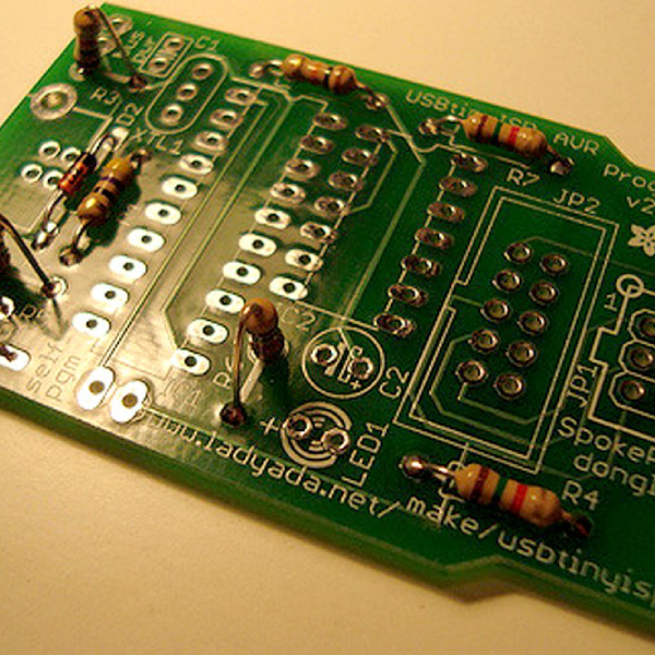
Zener diodes are not only about theory; they serve many practical purposes. These semiconductor devices can be found in a variety of applications. Their ability to conduct in reverse bias at a specific voltage makes them ideal for several key functions. Below are some common uses:
- Voltage Regulation: This is perhaps the most important application. Zener diodes keep voltage levels stable in circuits, ensuring devices operate safely.
- Overvoltage Protection: They protect sensitive electronics by diverting excess voltage away, preventing damage.
- Waveform Clipping: In signal processing, Zener diodes clip parts of waveforms to shape signals as needed.
- Power Supply Management: They help in controlling fluctuations, allowing stable power supply to delicate circuits.
- Reference Voltage: Zener diodes can provide a stable reference voltage for precise measurements in circuits.
Each application benefits from the key characteristics of Zener diodes—their Zener voltage and robust design. With these features, they excel in circuit protection and management, making them indispensable in electronics.
