How to test diode
Diodes are essential components in electronic circuits, allowing current to flow in one direction while blocking it in the opposite direction. Testing diodes is crucial to ensure their proper functionality and to identify any potential issues. Whether you’re a beginner or an experienced technician, this comprehensive guide will walk you through the process of testing diodes using various methods.
 Understanding Diodes
What is a Diode?
Definition: A diode is a semiconductor device that permits current to flow in one direction and blocks it in the opposite direction. It has two terminals: the anode and the cathode.
Types of Diodes: There are several types of diodes, including standard diodes, Zener diodes, Schottky diodes, and light-emitting diodes (LEDs). Each type has specific characteristics and applications.
Diode Symbol and Polarity
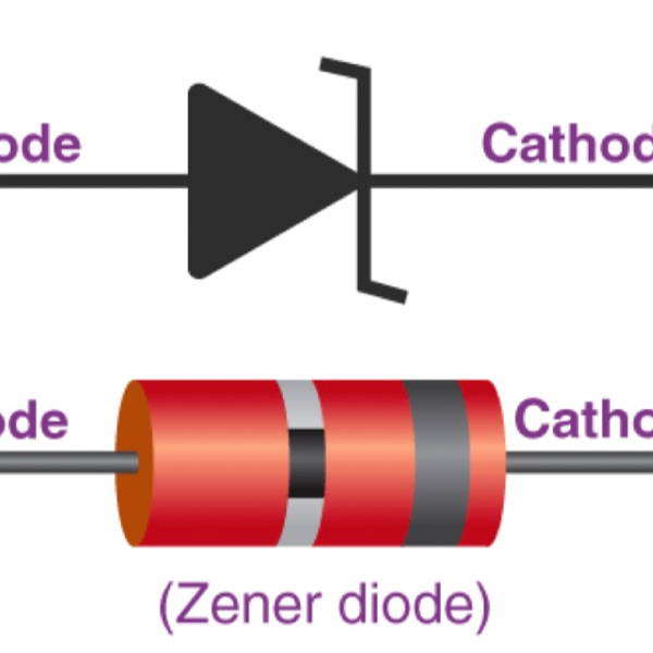
Symbol: The diode symbol consists of a triangle pointing towards a line. The triangle represents the direction of current flow (anode to cathode), and the line represents the blocking end (cathode).
Polarity: The anode is the positive terminal, and the cathode is the negative terminal. Identifying the polarity is crucial for testing and installing diodes correctly.
Tools and Materials Needed
Essential Tools
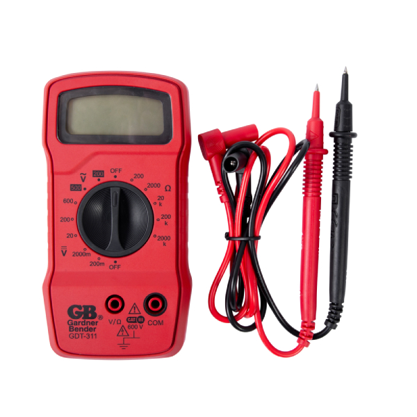
- Digital Multimeter (DMM)
- Analog Multimeter (optional)
- Breadboard and jumper wires (for circuit testing)
- Test leads
Materials
- Diodes for testing
- Datasheets for specific diode specifications
 Methods to Test a Diode
Using a Digital Multimeter (DMM)
Step 1: Prepare the Multimeter
Select Diode Mode: Turn the dial on your multimeter to the diode test mode, often indicated by a diode symbol.
Check Leads: Ensure the test leads are properly connected: the black lead in the COM (common) socket and the red lead in the V (voltage) socket.
Step 2: Identify the Diode’s Terminals
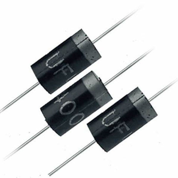
Identify Anode and Cathode: Most diodes have a marking such as a band to indicate the cathode. Refer to the datasheet if necessary.
Step 3: Test Forward Bias
Connect Leads: Touch the red (positive) lead to the anode and the black (negative) lead to the cathode.
Read Measurement: The multimeter should display a voltage drop (typically between 0.6V and 0.7V for silicon diodes). This indicates the diode is forward-biased and functioning correctly.
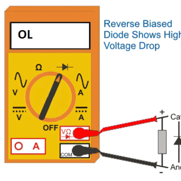
Step 4: Test Reverse Bias
Swap Leads: Reverse the leads, with the red lead on the cathode and the black lead on the anode.
Read Measurement: The multimeter should display “OL” or a very high resistance, indicating no current flows through the diode (reverse-biased). This confirms the diode’s ability to block reverse current.
Using an Analog Multimeter
Step 1: Prepare the Multimeter
Select Resistance Mode: Set the analog multimeter to the resistance (ohm) mode.
Zero Adjustment: Before testing, touch the leads together and adjust the needle to zero if necessary.
Step 2: Identify the Diode’s Terminals
Identify Anode and Cathode: As with digital multimeters, look for a marking such as a band to identify the cathode. Refer to the datasheet if needed.
Step 3: Test Forward Bias
Connect Leads: Place the red lead to the anode and the black lead to the cathode.
Read Measurement: The needle should deflect to a low resistance value, indicating the diode is forward-biased and conducting.
Step 4: Test Reverse Bias
Swap Leads: Connect the red lead to the cathode and the black lead to the anode.
Read Measurement: The needle should show a very high resistance or no deflection, indicating the diode is reverse-biased and blocking current.
 Testing Diodes in Circuit
Step 1: Power Off the Circuit
Disconnect Power: Ensure the circuit is powered off and fully discharged to prevent inaccurate readings and safety hazards.
Step 2: Identify the Diode
Locate Diode: Identify the diode within the circuit and note its orientation.
Step 3: Test with Multimeter
Forward Bias: With the circuit powered off, place the red lead on the anode and the black lead on the cathode.
Reverse Bias: Reverse the leads and measure again.
Circuit Impact: Be aware that other components connected in parallel with the diode may affect the readings. If uncertain, consider desoldering one end of the diode to isolate it for testing.
 Advanced Diode Testing
Using a Curve Tracer
Curve Tracer Use: A curve tracer can provide a detailed analysis of a diode’s characteristics by plotting its I-V (current-voltage) curve.
Settings and Safety: Follow the manufacturer’s instructions for setting up and using the curve tracer. Always follow safety precautions.
Pulsed Testing
Pulsed Method: This method involves applying short-duration pulses to test the diode’s response. It’s useful for high-power diodes or in-circuit testing without heating the component.
Equipment: Specialized equipment is required for pulsed testing, such as pulse generators and monitoring oscilloscopes.
Interpreting Diode Test Results
Good Diode
Forward Voltage Drop: Typical forward voltage drop for silicon diodes is between 0.6V and 0.7V. For Schottky diodes, it may be lower (0.2V to 0.3V).
Reverse Resistance: A good diode should show high resistance (open circuit) when reverse-biased.
Bad Diode
No Forward Voltage Drop: If the diode does not show a forward voltage drop, it may be open or damaged.
Low Reverse Resistance: If the diode shows low resistance or conductive behavior in reverse bias, it’s likely shorted or faulty.
Variable Readings: Inconsistent or fluctuating readings suggest a potential issue with the diode or poor connections during testing.
Common Diode Issues and Solutions
Shorted Diode
Symptom: The multimeter shows low resistance or continuity in both forward and reverse bias.
Solution: Replace the diode, as it can no longer block reverse current.
Open Diode
Symptom: The multimeter shows no reading or infinite resistance in both forward and reverse bias.
Solution: Replace the diode, as it has lost its ability to conduct current.
Leaky Diode
Symptom: The diode displays a forward voltage drop, but also shows a small current leakage or low resistance in reverse bias.
Solution: Replace the diode, as it may lead to circuit malfunction or instability.
Practical Applications of Diode Testing
Power Supplies
Rectification: Diodes are used in rectifiers to convert AC to DC. Testing ensures diodes function correctly in rectifier circuits.
Protection: Zener diodes provide overvoltage protection. Regular testing ensures they maintain their breakdown voltage.
Signal Processing
Switching: Diodes in switching circuits must be verified to ensure they conduct and block current as expected.
Clipping and Clamping: Diodes used for signal clipping or clamping should be tested to confirm their voltage regulation.
LED Testing
Forward Bias Lighting: LEDs should illuminate when forward-biased. Testing ensures proper function in lighting and indicator applications.
Color and Intensity: Testing various LEDs for consistent color and brightness helps maintain uniformity in displays and signage.
Tips for Accurate Diode Testing
Proper Connections
Firm Contact: Ensure test leads make firm and clean contact with the diode terminals.
Observe Polarity: Always observe the correct polarity when testing.
Use Appropriate Tools
Quality Multimeter: Use a reliable and accurate multimeter for measuring diodes.
Isolate Diodes in Circuit
Desolder One End: If in-circuit testing results are inconclusive, desolder one end of the diode to isolate it for accurate testing.
 Safety Precautions
Handling Components
Power Off: Always power off the circuit and ensure capacitors are discharged before testing.
Avoid Static: Use anti-static measures, such as grounding straps, when handling sensitive components like diodes.
Working Environment
Ventilation: Work in a well-ventilated area, especially when using tools that may produce fumes.
Protective Gear: Wear safety glasses and protective gear when working with soldering equipment.
Conclusion
Testing a diode is an essential skill for anyone working with electronic circuits. By using a digital or analog multimeter, you can determine whether a diode is functioning correctly or if it needs to be replaced. This comprehensive guide provides the knowledge and steps needed to test diodes accurately and effectively. Always prioritize safety, follow proper procedures, and interpret your results carefully. With these skills, you can ensure the reliability and efficiency of your electronic projects. Happy testing!