Introduction to Zener Diodes
Zener diode circuit are unique components in the electronic world. They allow current to flow in both normal and reverse directions. This special feature makes Zener diodes critical for various circuits. And it’s not just in current flow that they stand out. When it comes to voltage regulation, Zener diodes are kings.
Their operation hinges on the ‘Zener Effect’. This occurs when a diode conducts electricity in reverse once a certain voltage, called the ‘Zener Voltage’, is reached. Unlike regular diodes, Zener diodes are designed to handle this reverse flow without damage. This means they serve as a reliable, controllable barrier against unwanted voltage spikes.
The beauty of Zener diodes lies in their simplicity and versatility. They require minimal external components to function. Sometimes, just a resistor is enough. Their widespread use in circuits is due to their ability to stabilize voltages, making them suitable for a broad range of applications.
Understanding Zener diodes is the first step to mastering their potential. The rest of this blog will explore their inner workings, their role in circuits, and tips for designing with them effectively.
Zener Diode Operation and Breakdown Mechanisms
Understanding the operation and breakdown mechanisms of a zener diode is essential for electronic circuit design. These mechanisms define how zener diodes behave under different conditions and thus dictate their applications.
Zener Effect and Zener Voltage
The Zener effect is a distinct feature of zener diodes. This effect allows the diode to conduct in reverse when a specific voltage is applied. We call this voltage ‘Zener Voltage’. It is the key to a diode’s voltage regulation abilities. Zener Voltage varies with each diode and determines at what point the diode will allow reverse current to flow. Thus, knowing the Zener Voltage is crucial for circuit design.
Avalanche Breakdown
Avalanche breakdown is another breakdown mechanism in zener diodes. It happens at a high reverse voltage. This causes free electrons to move fast and hit other atoms. This action frees more electrons and creates a chain reaction. This allows for a sudden surge in current. Zener diodes are built to handle this increase without breaking down. In diodes with Zener voltage over 6 volts, this is often how they conduct in reverse.
Characteristics and Specifications of Zener Diodes
When selecting Zener diodes for electronic circuits, understanding their characteristics and specifications is vital. These details guide the diode’s use, ensuring it meets the circuit’s demands.
V-I Characteristics Interpretation
The V-I (voltage-current) characteristics show how a Zener diode behaves across various voltages. A graph plots the current that flows against the applied voltage. For Zener diodes, the V-I graph splits into two parts: the forward-biased region and the reverse-biased region. In the forward region, they act like normal diodes. In reverse, they allow a controlled current to pass once the Zener voltage hits. This controlled current remains steady, even if the voltage keeps rising.
Key Specifications for Circuit Design
Key specs to consider for Zener diodes include:
- Zener Voltage (Vz): This is the specific voltage at which the diode allows reverse current.
- Maximum Power Dissipation: It tells how much power the diode can handle before it overheats.
- Maximum Current (Iz max): The top limit of current that can flow through the diode without damage.
- Zener Impedance (Zz): This is the diode’s resistance in the Zener breakdown region.
Selecting the right diode requires matching these specs to your circuit’s needs. For instance, a higher power dissipation may be essential for a high-power circuit. Similarly, the Zener voltage should align with the voltage regulation requirements of your circuit.
Designing Basic Zener Diode Circuits
When building electronic circuits, Zener diodes are often an essential element. These diodes can create stable voltage references or protect circuits from voltage spikes. Below, we explain how to design basic Zener diode circuits.
Simple Zener Diode Voltage Reference
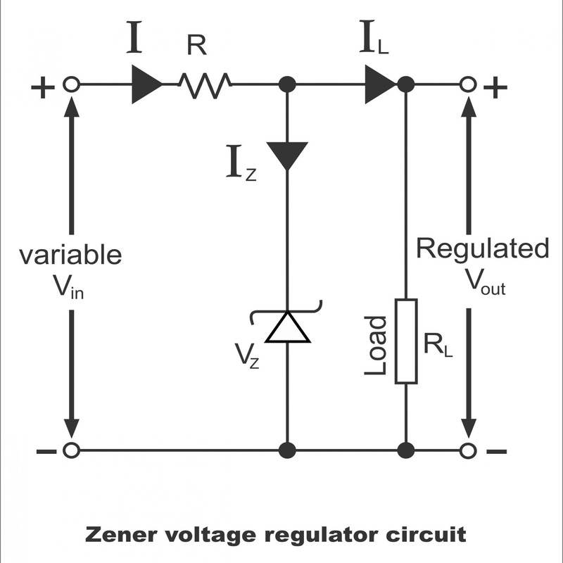
A simple Zener diode circuit can effectively provide a stable voltage reference point. This basic setup requires a Zener diode and a resistor in series. The diode acts as the voltage reference, while the resistor limits current. It’s important to select a resistor with an appropriate value. This ensures the diode operates within safe limits and achieves the desired voltage regulation.
Calculating Resistor Values
Choosing the right resistor for a Zener diode circuit is crucial. To calculate the required resistor value, follow these steps:
- Subtract the Zener voltage from the supply voltage to find the voltage across the resistor.
- Decide on the current for the Zener diode, typically above 5 mA, for it to regulate properly.
- Choose a resistor value that gives the correct current at the voltage found in step one.
- Make sure the Zener diode’s power dissipation doesn’t exceed its maximum rating when you pick the current.
- Remember, the resistor also dissipates power. Its wattage rating must be high enough to handle this without overheating.
By carefully performing these calculations, you ensure your Zener diode circuit functions correctly and safely.
Applications of Zener Diodes in Electronic Circuits
Voltage Regulation
Zener diodes excel as voltage regulators. They ensure a stable voltage supply in electronic circuits. Here’s how this works: When circuit voltage rises above the Zener voltage, the diode starts conducting. This action keeps the voltage constant at the Zener level. These diodes can handle changes in load conditions without fluctuating voltage. You’ll find them in power supplies, where accurate voltage is crucial.
For voltage regulation, the diode’s Zener voltage must match the desired level. It’s connected in parallel with the load. As voltage increases, the diode maintains a steady output by conducting excess current.
Overvoltage Protection
Protecting circuits from overload is another Zener diode use. They act as safety valves, guarding against spikes in voltage. If the input voltage jumps too high, the Zener diode conducts. This limits the surge and protects sensitive components. Without Zener diodes, costly damage could occur from voltage spikes.
This process uses the Zener’s ability to handle reverse current without harm. It’s often used in series with fuses or breakers that cut off high voltage. This combination provides a solid defense for electronic devices.
By applying Zener diodes in these ways, circuits gain reliability and longevity. Whether regulating voltage or shielding from overvoltage, Zener diodes are key to circuit safety and functionality.
Advanced Zener Diode Circuit Configurations
When diving deeper into Zener diode applications, advanced circuit configurations come into play. These setups take the basic Zener diode functionality and enhance it for specific demands. This section will explore two such configurations that offer improved performance in voltage regulation and overvoltage protection.
Shunt Regulator with Transistor Buffer
A shunt regulator using a transistor buffer is a common setup. It boosts a Zener diode circuit’s current handling capabilities. This design involves a Zener diode connected to the base of a transistor. The transistor acts like a current amplifier. It ensures the Zener diode regulates voltage without handling the full load current itself.
Here’s a quick guide on how to build this circuit:
- Connect the Zener diode to the transistor base.
- Use a resistor to feed the diode and set the reference voltage.
- The transistor buffers the output, providing more current to the load.
- Adjust the resistor value to control the flow to the Zener diode.
This setup is great for circuits where the Zener diode alone can’t provide enough current.
Overvoltage Protection with SCR
For protecting against sudden voltage spikes, the Zener-SCR combination is effective. SCR stands for Silicon Controlled Rectifier. This circuit triggers under high voltage, safeguarding sensitive components.
Setting up the overvoltage protection:
- Place the Zener diode to detect the overvoltage.
- Connect an SCR to quickly divert or cut off the excess current.
- The Zener diode controls the SCR gate, firing it when voltage exceeds safe limits.
This configuration is a safety net that reacts fast to protect your electronic circuits.
By incorporating these advanced Zener diode circuit designs, engineers can tackle more complex voltage issues. These configurations add layers of stability and security to any electronic system.
Best Practices for Zener Diode Circuit Design
When designing circuits with Zener diodes, following best practices is key. These practices ensure the circuits work as intended. They protect the diodes and other components from damage. Here are critical tips for optimal zener diode circuit design.
Stabilizing Zener Diode Voltage
To stabilize the Zener diode voltage, consider these points:
- Choose a Zener diode with the right Zener voltage for your circuit needs.
- Use a resistor in series with the Zener to limit current flow through the diode.
- Match the diode’s power rating to the circuit’s power needs to prevent overheating.
- Add a capacitor in parallel to the Zener diode for filtering and reducing voltage spikes.
Keep the current through the Zener diode constant for a stable voltage output. This can be done by connecting a resistor or a constant current source.
Ensuring Proper Current Flow
To make sure the Zener diode conducts properly, follow these steps:
- Make sure the Zener diode’s minimum current rating is met. This helps it to regulate accurately.
- Don’t let the current exceed the maximum limit the Zener diode can handle.
- Balance the current flow, using resistors or current sources, to achieve stable operation.
By following these guidelines, your Zener diode circuit should work reliably. These best practices help achieve the desired voltage regulation and circuit protection.
