Introduction to Diodes and Their Importance
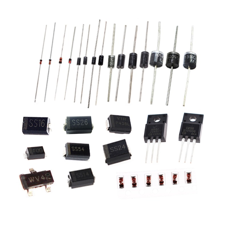
Diode Curve play a crucial role in modern electronics. Their core function is to allow current to flow in one direction only. This unique ability makes them vital in converting alternating current (AC) to direct current (DC). Without diodes, many of our daily-use electronic devices would not work.
Their inclusion in circuits aids in preventing damage from electrical surges. Diodes also ensure that electronic signals move efficiently and consistently. For example, they are key components in radios, televisions, and power supply units.
Understanding the ‘diode curve’ is essential for electronics enthusiasts and professionals alike. It is a graphical representation of a diode’s behavior under various voltage conditions. By examining the diode curve, one can anticipate how a diode will perform in a circuit.
This makes diodes not only fundamental in theory but indispensable in practical electronics. Their versatility extends to tasks such as circuit protection, voltage regulation, and signal rectification. This is why a thorough grasp of diode characteristics, as illustrated by the diode curve, is important.
Basic Principles of Diode Operation
The basic operation of diodes centers on the semiconductor material inside them. This material forms what we call a p-n junction. A p-n junction is made from a piece of silicon that is doped with two types of impurities. One side is p-type, with positive charge carriers, while the other is n-type, with negative electrons.
When no voltage is applied across a diode, the p-n junction’s charge carriers are in balance, creating a depletion zone. This zone acts as an insulator, preventing current from flowing.
As soon as we apply voltage in the correct direction, it pushes the charge carriers away from the junction. This is called forward biasing the diode. In forward bias, current flows easily from the p-type side to the n-type side.
Conversely, if voltage is applied in the opposite direction, known as reverse bias, it pulls the charge carriers towards the junction, strengthening the depletion zone. In reverse bias, current flow is blocked. This unique behavior underlies the diode curve that portrays how current flows through a diode at varying voltage levels.
Every diode’s operation is governed by these principles, which precisely govern the relationship between voltage and current as illustrated in the diode curve. Understanding these basics is key to grasping more complex diode curve concepts.
The Diode IV Curve Explained
To delve deeper into diode curve characteristics, it’s essential to understand the diode IV (current-voltage) curve. This curve offers a visual representation of the relationship between the voltage across the diode and the current that passes through it. The IV curve is split into three critical regions, each highlighting a unique aspect of a diode’s behavior under different electrical conditions.
The Forward Bias Region
In the forward bias region of the diode curve, the voltage is applied in a manner that supports current flow through the diode. Initially, when a small forward voltage is applied, the current remains minimal, reflecting the overcoming of the diode’s threshold voltage. As the voltage increases beyond this initial threshold, the current begins rising rapidly, showing the ease of current flow through the diode in this region. This is the standard operating region for diodes when they are used to conduct electrical current in one direction.
The Reverse Bias Region
Contrary to the forward bias, the reverse bias region is defined by the application of voltage in the opposite direction, discouraging current flow. Here, the diode’s behavior shifts dramatically. A small leakage current may still flow, but the diode essentially acts as an insulator, maintaining a high resistance. The reverse bias region of the diode curve remains fairly flat, indicating the effectiveness of the diode in blocking current flow in this state.
Factors Affecting Diode Curve Shape
Several factors can affect the shape of a diode curve. These include temperature, materials used, and variations in manufacturing processes. Understanding these influences is vital for predicting diode behavior in diverse operating conditions.
Temperature Effects
Temperature changes play a significant role in modifying diode curve characteristics. As temperature rises, the diode’s threshold voltage typically decreases. This causes the diode to allow current to flow at lower voltages in forward bias. Conversely, in reverse bias, higher temperatures can lead to increased leakage currents. Therefore, it’s crucial to consider temperature when assessing diode performance.
Material Composition
The semiconductor material out of which a diode is made also affects its IV curve. Silicon and germanium are common materials, each with distinct properties. Silicon diodes have a higher threshold voltage than germanium diodes. Moreover, the choice of semiconductor dictates the diode’s sensitivity to temperature changes and breakdown voltage.
Diode Manufacturing Differences
Lastly, no two diodes are identical due to differences in manufacturing. Inconsistencies in doping levels, impurities, and junction sizes can result in variations in diode curves. These manufacturing peculiarities may alter the precise point at which a diode enters forward or reverse bias and its overall current-voltage response.
Analyzing Diode Curve for Different Diode Types
When analyzing diode curves, it’s crucial to recognize that not all diodes are the same.
Zener Diodes
Zener diodes have a unique diode curve, especially in the breakdown region. Unlike regular diodes, Zener diodes are designed to work in this area. Their breakdown voltage is much lower, and the effect is precise and controlled. This means they can stabilize voltage in a circuit without damage.
Schottky Diodes
Schottky diodes are known for their low forward voltage drop. This makes their diode curve look quite different from standard diodes. They start conducting at much lower voltages, and their curve rises sharply. They are fast and great for high-frequency applications.
Tunnel Diodes
Tunnel diodes are another special type with a distinct diode curve. They show a negative resistance region. This means their current decreases as voltage increases, up to a point. This unique behavior is used in high-speed electronics and oscillators.
Practical Applications of Diode Curve Analysis
The diode curve is not just a theoretical concept. It has practical applications in electronic circuit design and function. Here, we delve into three key applications where understanding the diode curve is crucial.
Circuit Protection
Diode curves are essential in designing circuits for protection against electrical surges. Diodes allow current to flow in a preferred direction, shielding sensitive components from potential harm. For instance, when a voltage spike occurs, the diode enters its reverse bias region, preventing the surge from passing. This protective behavior is predictable through the diode curve, ensuring the safety of electronic devices during unexpected voltage spikes.
Voltage Regulation
Voltage regulation is another area where diode curves play a significant role. Regulator circuits often use Zener diodes because their breakdown region can be engineered to a specific voltage. By analyzing a Zener diode’s curve, one can determine the precise voltage at which it will conduct in reverse bias—this allows for stable voltage across components, critical for consistent device performance.
Signal Rectification
Signal rectification is perhaps the most common application of diodes and their characteristic curves. Diodes convert AC signals into DC by permitting current flow only in one direction—forward bias region. The shape of the diode curve determines at what voltage the diode will begin to conduct and how effectively it will rectify the AC signal. This is vital for everything from power supplies to audio equipment, making rectification a fundamental use of the diode curve in electronics.
How to Measure and Plot a Diode Curve
To understand a diode’s performance, measuring and plotting its curve is vital. Here’s how you can do it.
Required Instruments
To begin, gather the necessary equipment. You will need:
- A digital multimeter (DMM) for precise voltage and current readings.
- A variable power supply to apply different voltage levels to the diode.
- A breadboard and jumper wires for easy circuit assembly.
- The diode that you wish to test.
- A resistor to limit current and protect the diode from excessive current.
- Graph paper or software for plotting the diode curve.
Ensure you have a clean, well-lit workspace and all instruments are calibrated.
Step-by-Step Procedure
Follow these steps to measure and plot the diode curve:
- Connect the diode to the breadboard.
- Attach the resistor in series with the diode to restrain the current.
- Link the variable power supply across the series combination.
- Gradually vary the power supply and note the voltage and current from the DMM.
- Begin with a small voltage and increase in steady increments.
- Record current and voltage values for each increment in forward bias.
- Repeat the process for reverse bias, noting leakage currents.
- Plot the recorded values on graph paper or input them into plotting software.
- Sketch the curve using the plotted points to visualize the diode behavior.
By following these steps, you can generate a diode curve that accurately reflects its characteristics under different electrical conditions. Understanding this curve is crucial for applications such as circuit protection, voltage regulation, and signal rectification as previously discussed. Keep safety in mind and always ensure your instrumentation is set up correctly to prevent any damage to the diode or equipment.
Conclusion and Summary of Key Points
In this blog, we explored the essential aspects of diode curves and their significance in electronics. We started by understanding the basic operation of diodes, focusing on their one-way current flow capability which is crucial in numerous electronic applications like AC to DC conversion.
We then delved into the diode IV curve, highlighting three main regions: the forward bias region where diodes conduct electricity, the reverse bias region where they block current, and the breakdown region which is critical for certain types of diodes like Zener diodes for voltage regulation.
Factors such as temperature, material composition, and manufacturing variances were discussed. These elements can significantly affect a diode’s performance, influencing the shape and behavior of the diode curve under various conditions.
Our analysis extended to different diode types including Zener, Schottky, and Tunnel diodes, each with unique characteristics beneficial for specific applications. Practical applications of the diode curve in circuit protection, voltage regulation, and signal rectification were also covered, showcasing how diode characteristics are essential for designing and optimizing electronic circuits.
Finally, we provided a step-by-step guide on how to measure and plot a diode curve, a process critical for anyone working with or designing electronic circuits involving diodes.
Understanding diode curves is not just theoretical but a practical necessity for electronics professionals and enthusiasts. This knowledge ensures better design, troubleshooting, and optimization of electronic systems.
