What is SMD Diode Polarity?
SMD diode polarity indicates the direction of current flow in the diode. It is critical for the correct operation of the diode in a circuit. Ensuring correct polarity prevents potential damage and ensures the diode functions as intended.
In this article, we’ll unpack the importance of correctly identifying SMD diode polarity and how misalignment can lead to circuit failure. We will cover the common methods for recognizing diode polarity through markings, color codes, and orientation indicators that are pivotal for proper installation. Detailed guides will help you navigate the complexities of soldering and placing SMD diodes in your projects.
Additionally, we will delve into types of SMD diodes, including Zener, Schottky, and rectifier diodes, along with their specific circuit applications. This knowledge is essential for selecting the right diode for your electronic projects. We’ll also provide tips for reading SMD diode datasheets to facilitate accurate components selection. Whether you are a hobbyist, engineer, or student, mastering SMD diode polarity will enhance the reliability and efficiency of your electronic designs.
Understanding Anode and Cathode in SMD Diodes
The anode in an SMD diode is the positive end where the current enters, and the cathode is the negative end where current exits. It’s vital to connect these correctly to maintain proper functioning.
Importance of Correct Polarity in Circuit Functionality
Correct SMD diode polarity ensures that electrical circuits function efficiently and safely. Incorrect polarity can cause malfunctions and potentially damage the entire electronic system.
Identifying Polarity on Diodes
Identifying the correct polarity is crucial for SMD diodes to function as intended in a circuit. Here are some methods to determine diode polarity:
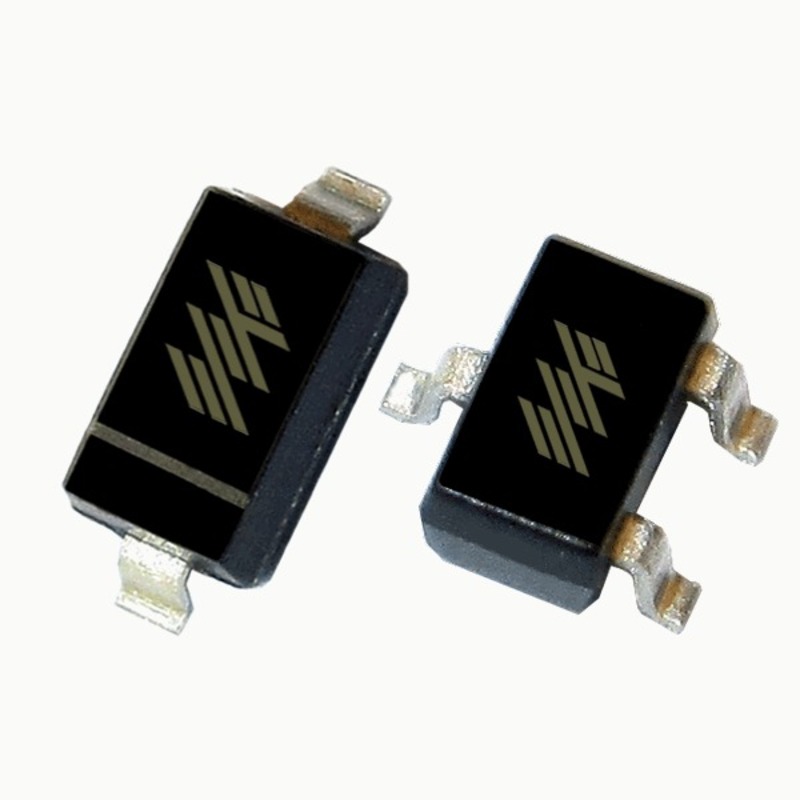
Visual Indicators: Markings and Notches
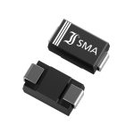
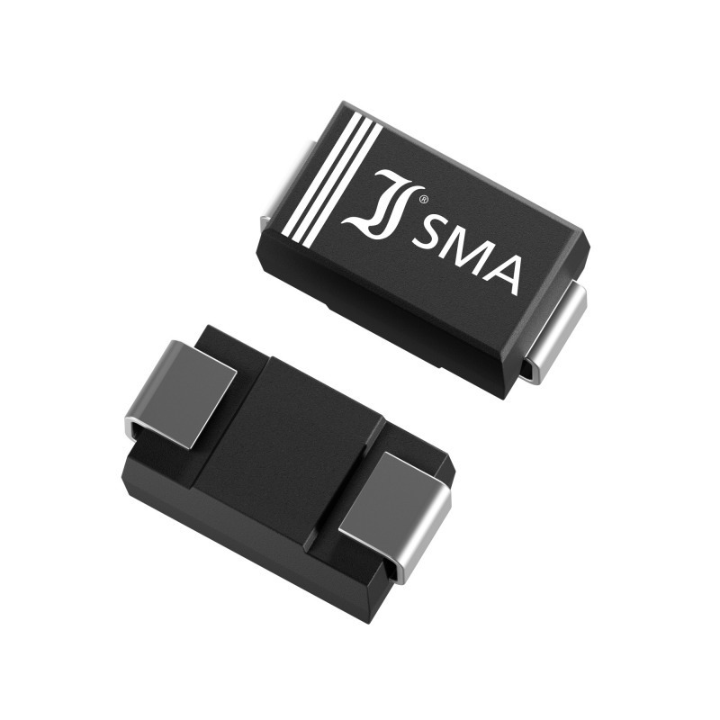
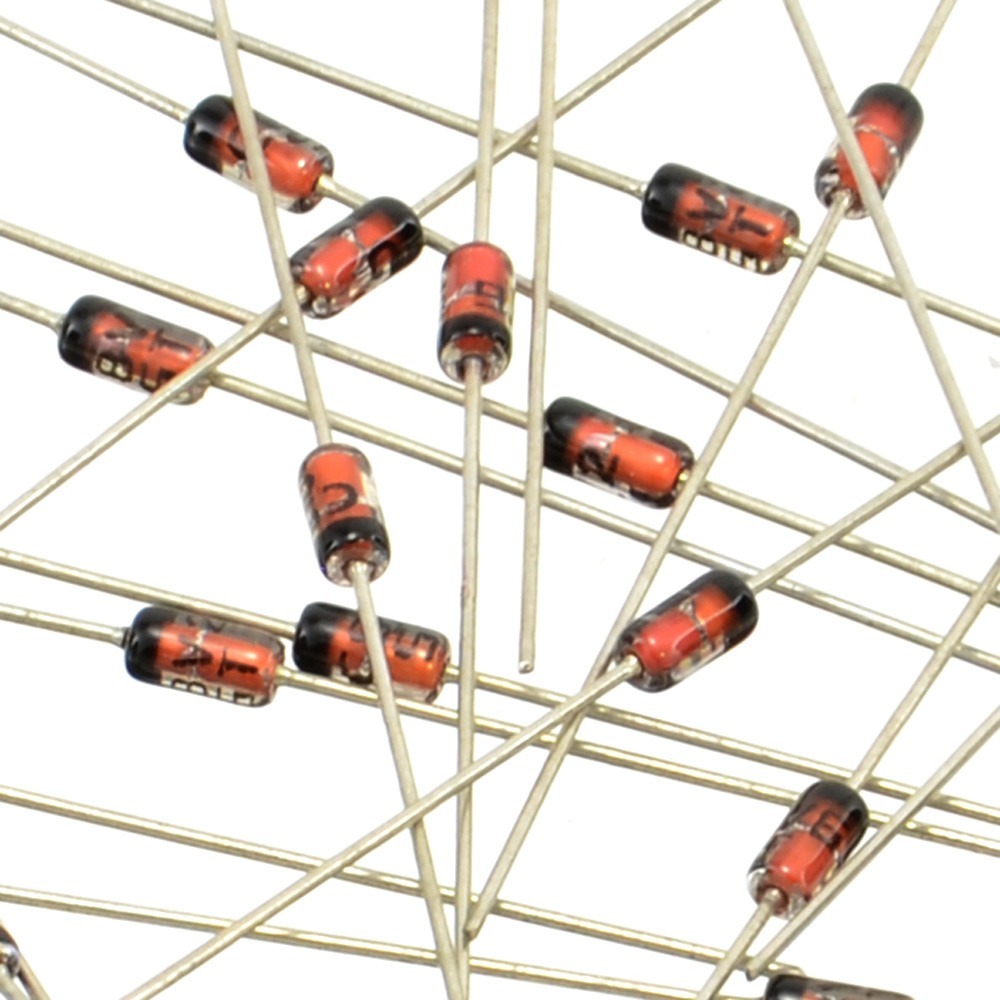
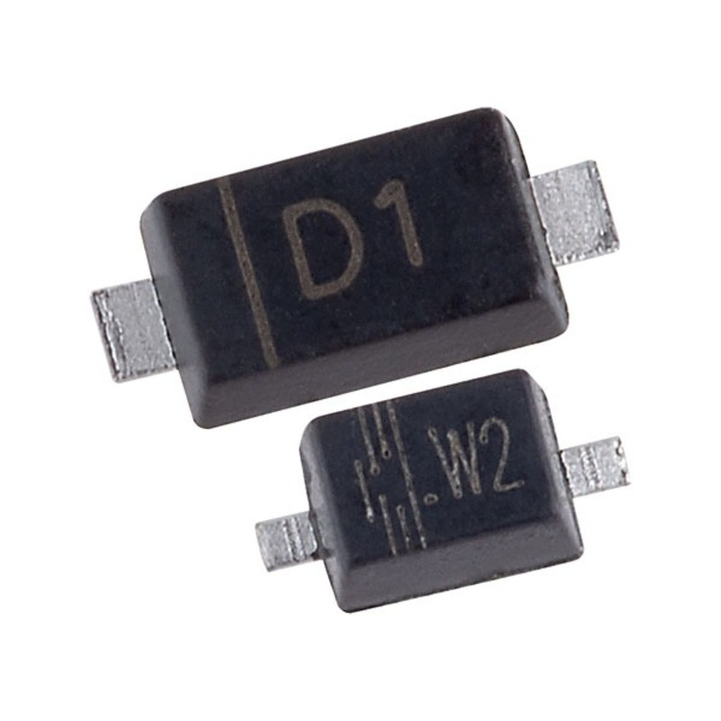
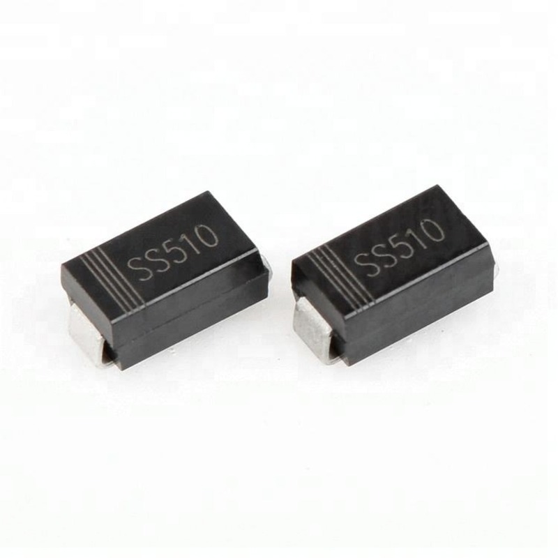
Most SMD diodes come with clear visual indications to help identify their polarity. Look for unique markings such as a line, dot, or notch on the diode’s body. These indicators usually denote the cathode side, guiding you in placing the diode correctly on the PCB.
- A line or stripe typically marks the cathode end.
- A dot or notch may also indicate the cathode, depending on the manufacturer.
- Some diodes might have color bands, where a specific color denotes the cathode.
Using Multimeters for Polarity Testing
A reliable method to test for SMD diode polarity is with a multimeter. By setting the multimeter to the diode testing mode, you can check which lead corresponds to the anode and which to the cathode.
- Connect the multimeter’s positive lead to one side of the diode.
- Connect the negative lead to the other side.
- A forward bias reading suggests you have found the anode.
- If the multimeter shows no reading or OL (open loop), reverse the leads.
Interpreting Schematic Symbols
Schematic symbols in circuit diagrams are also helpful in determining SMD diode polarity. The symbols provide directional cues for correct placement.
- Look for the triangle with a line at one end, which represents the diode in the diagram.
- The line denotes the cathode, and the opposite, the tail end of the triangle, indicates the anode.
- Arrows may also be used, pointing towards the cathode.
Common Practices for Diode Installation
Proper diode installation is vital for the function and longevity of electronic circuits. Here, we detail the common practices that ensure diodes are installed correctly, enhancing your electronic designs.
Correct Placement of Anode and Cathode
Always check that the anode (positive) and cathode (negative) ends are in their proper places. Errors here can cause the circuit to fail. The anode should explicitly connect to the voltage source, and the cathode should lead to the ground.
Double-Checking Polarity Before Soldering
Before you solder, double-check the polarity. This preventive step saves time and money by avoiding damage from incorrect diode placement. It’s useful to use a checklist or have a second verification by another technician.
Using Polarity Markings on PCBs
PCBs often have polarity markings that are easy to follow. These markings guide you on where the anode and cathode should be. Relying on these guides will reduce errors and ensure consistency in diode installation.
Avoiding and Addressing Installation Mistakes
Ensuring accurate installation of SMD diodes requires awareness of common errors and solutions. Even seasoned technicians can encounter issues if attention to detail wanes.
Common Errors in SMD Diode Installation
- Reversed Polarity: This occurs when the anode and cathode are swapped during installation. It prevents the diode from functioning and can damage the circuit.
- Poor Soldering: Inadequate soldering can lead to loose connections that compromise the diode’s performance.
- Ignoring PCB Markings: Sometimes, technicians overlook the polarity markings on PCBs, leading to incorrect placements.
- Using Incorrect Diodes: Not all diodes are suitable for every application. Using a diode that isn’t rated for the specific use can lead to failure.
Rectifying Incorrect Polarity Connections
- Immediate Correction: If you discover reversed polarity before powering the circuit, desoldering and correcting the placement is straightforward.
- Circuit Testing: After any diode installation, testing the circuit helps identify and rectify errors before they cause damage or inefficiency.
- Regular Training: Regular workshops and training sessions for technicians can reduce installation errors. It keeps everyone updated on best practices.
- Quality Checks: Implement routine checks during multiple stages of the assembly process. This helps catch mistakes early.
By following these guidelines, you can minimize mistakes and ensure optimal performance of SMD diodes in your projects.
Advanced Tips for SMD Diode Use
When it comes to SMD diode installation, a set of advanced practices can ensure optimal performance and longevity. Here are expert tips for proficient use and integration of SMD diodes.
Heat Management in Diode Installation
Heat is a crucial factor that affects SMD diodes during soldering and operation. Managing heat ensures diodes do not suffer from thermal stress which might impair their function.
- Use Heat Sinks: To dissipate heat effectively, attach heat sinks to diodes especially in high-power applications.
- Control Soldering Heat: Apply heat carefully during soldering to prevent damage. Use tools that allow for temperature control.
- Monitor Operating Temperature: Ensure the diode’s environment doesn’t exceed its maximum operating temperature by using thermal cameras or sensors to monitor.
Integrating Diodes on Complex PCBs
As PCBs become more complex, integrating SMD diodes requires attention to detail and proper planning.
- PCB Design: Prioritize diode placement in PCB design to allow for heat dissipation and easy access for testing.
- Component Spacing: Provide enough space between diodes and other components to prevent interference and allow for airflow.
- Trace Sizing: Ensure traces are appropriately sized to handle the current without causing overheating which could lead to diode failure.
By focusing on these advanced tips, one can significantly improve the efficiency and durability of diodes within electronic circuits.
Conclusion
Recap of Key Points
In this guide, we explored the crucial aspects of SMD diode polarity, highlighting the importance of correctly identifying and installing these components in electronic circuits. Key takeaways include:
- Anode and Cathode Understanding: Knowing where the current enters and exits the diode is fundamental.
- Visual Indicators: Markings, notches, or color bands help identify diode polarity quickly.
- Use of Multimeters: They are a reliable tool for testing and confirming the correct orientation of diodes.
- Schematic Symbols: These provide visual guides on circuit diagrams to aid in correct diode placement.
- Heat Management: Proper heat handling during soldering ensures diode longevity and performance.
By adhering to these practices, you can avoid common errors such as reversed polarity and poor soldering, thus enhancing the functionality and reliability of electronic devices.
Final Thoughts on Efficient Diode Installation
Achieving efficient diode installation not only protects the components but also ensures optimum circuit performance. Emphasizing regular training, adherence to PCB markings, and thorough testing are vital practices. These efforts culminate in more reliable and robust electronic designs, reducing potential rework and increasing device longevity. Remember, meticulous attention to detail in diode installation will lead to higher efficiency and fewer operational interruptions in electronic applications.
