Introduction to Diode IV Curves
The diode IV curve is an essential tool for understanding diodes. It plots voltage against current, showing how a diode responds to different voltage levels. Diodes allow current to flow in one direction while blocking it in the reverse. This behavior creates a specific curve on a graph.
In simple terms, the curve starts at zero and begins to climb as the forward voltage increases. At a certain point, called the threshold voltage, the current rises sharply. Reverse bias shows little current until a breakdown occurs. This is a form of electrical characterization that tells us much about a diode.
When designing circuits, knowing the IV characteristics can be pivotal. It influences decisions about which diode to use. Diode IV curves vary by type, so recognizing differences helps in choosing the right diode for a given application.
Studying these curves, engineers ensure that diodes function properly within their systems. Without this knowledge, diodes could fail, leading to system errors or damages. Each part of the curve reveals information about how a diode will handle electricity in a circuit.
To summarize, diode IV curves are vital for selecting and using diodes correctly. They help predict system behavior and avoid potential issues. As we delve deeper into the diode IV curve, we will explore its key parameters and applications in circuit design.
Fundamentals of Diode Operation
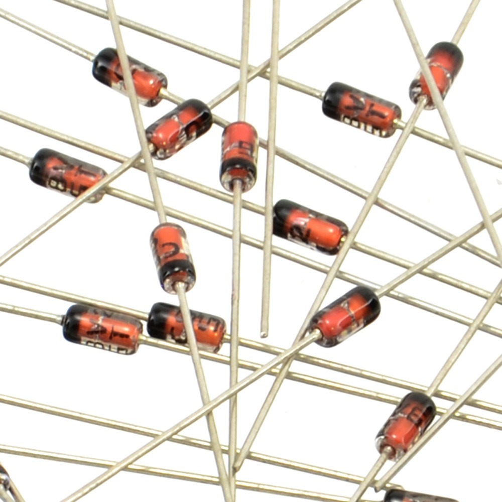
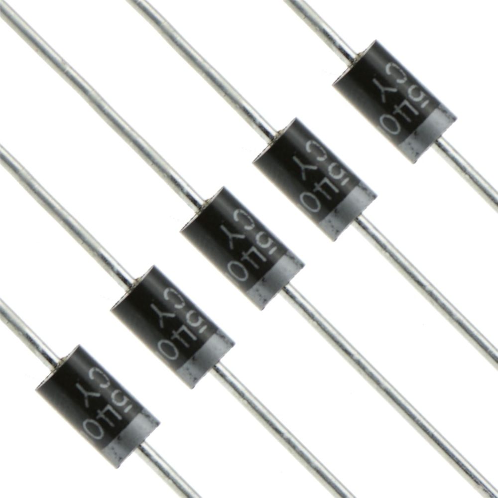
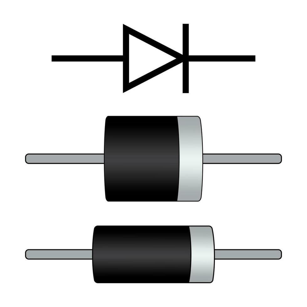
To understand how diodes work, we need to look at their basic operation. A diode is a semiconductor device that allows electrical current to flow in only one direction. It does this through the use of a p-n junction, which is the interface between two types of semiconductor material: p-type and n-type. The p-type semiconductor is rich in positive charge carriers, while the n-type is rich in negative charge carriers.
When no voltage is applied, the p-n junction creates a barrier that prevents current flow. Applying a forward voltage reduces this barrier, letting current pass. But, if we reverse the voltage, the barrier strengthens, which blocks the current. This selective allowance of current is what we call the diode’s rectifying property.
Moreover, the diode has what is known as a ‘forward bias’ condition. In this state, the diode’s resistance is low, and it easily conducts electricity. Conversely, when the diode is ‘reverse biased,’ its resistance is high, preventing current from passing through. This is crucial for diode iv curve analysis, as the curve shows the relationship between the voltage across the diode and the current that flows through it under these biases.
The fundamental operation of diodes is at the heart of their utility in electronic circuits. They are used to steer current, protect against reverse voltage, and convert alternating current (AC) to direct current (DC), among other roles. By mastering these principles, engineers can harness the diode iv curve to ensure the diode performs reliably in its intended application.

Key Parameters in Diode IV Curves
Understanding the diode IV curve is pivotal in predicting how a diode behaves under different conditions. Key parameters that govern the shape and information contained within a diode IV curve include threshold voltage, breakdown voltage, and maximum current. These elements are critical for engineers and technicians to grasp in order to select the proper diode for their specific applications and to forecast its performance.
Threshold Voltage: This is the point where the diode starts to conduct significantly and the current increases rapidly with a small increase in voltage. It’s essential for determining at what voltage a diode will efficiently start to allow current through.
Breakdown Voltage: Diodes are designed to block current in reverse bias until a certain voltage, known as the breakdown voltage, is reached. It is the point where the diode begins to conduct in reverse, which can potentially lead to failure if the diode is not meant to operate in this regime.
Maximum Current: This is the maximum amount of current that can flow through the diode when it is forward biased without causing damage. It helps in ensuring that the diode is not subjected to more current than it can handle.
These parameters are integral to diode iv curve analysis and aid engineers in understanding limits and operations of their diode components. The diode iv curve serves as a roadmap, providing necessary insights for effective circuit design and reliable electronic systems.
The Role of the Diode IV Curve in Circuit Design
The diode IV curve is crucial for designing electronic circuits. Engineers use it to determine how diodes will behave in different scenarios. The curve assists in choosing the right diode for a specific role within the circuit. It shows how the diode reacts to voltage changes and the current it can safely carry.
In circuit design, safety and efficiency are top priorities. The diode IV curve helps to guarantee both by revealing the diode’s operating boundaries. For example, designers can see the maximum current a diode can handle. Going beyond this could cause the diode to overheat or fail.
Beyond safety, the curve aids in achieving the desired performance. It shows at which voltage the diode will start to conduct or block current. This is vital for rectification tasks, where diodes convert AC to DC. It is also important for voltage regulation and signal modulation in more complex electronics.
Diode IV curves also inform about the speed of response. Fast-switching diodes are needed in digital circuits, where they have to turn on and off quickly. The curve reflects this capability, allowing engineers to pick the best-suited diode.
Overall, the diode IV curve is not just a piece of technical data. It is a tool that enables the creation of reliable, high-performing circuits. By understanding the curve, engineers ensure that the diode fulfills its role effectively within the electronic system.

Types of Diodes and Their IV Characteristics
Diodes come in various types, each with unique IV characteristics. Understanding these differences is crucial for choosing the right diode for specific applications. Here are some common types of diodes and their respective IV curve traits:
- Standard Rectifier Diodes: These are the most common diodes used mainly for converting AC to DC. Their IV curves show a sharp threshold as they start to conduct at a specific forward voltage.
- Zener Diodes: Zener diodes are designed to conduct in reverse when a certain breakdown voltage is reached. Their IV curves are invaluable for voltage regulation, as they clearly show the breakdown voltage beyond which they start to conduct.
- Schottky Diodes: Known for their low forward voltage drop and high-speed switching, Schottky diodes are ideal for high-frequency applications. Their IV curves tend to rise more steeply at lower voltages compared to standard diodes.
- Light-Emitting Diodes (LEDs): LEDs are unique in that they emit light when forward biased. Their IV curves help determine the forward voltage at which light emission begins effectively.
- Photodiodes: Used primarily in optical applications, photodiodes are designed to convert light into electrical current. Their IV curves are essential for understanding how they respond to various light intensities.
Each type of diode serves a specific function, and their IV characteristics provide critical insights into their performance in different circuits. By analyzing these curves, engineers can make informed decisions on diode selection tailored to their circuit design needs.
Analyzing Real-World Diode IV Curves
Real-world analysis of diode IV curves is crucial in practical electronics. It helps engineers confirm theoretical predictions and understand diode behavior in actual applications. This analysis involves comparing lab-derived curves with those obtained under real conditions.
Collecting Data: In real-world scenarios, collecting accurate IV curve data requires precise instruments. Engineers use voltmeters and ammeters to capture voltage and current accurately. They also ensure the diode operates within its intended environment to mimic actual operating conditions.
Analysis Tools: Engineers employ software tools to analyze the recorded data. These tools help visualize the curve, allowing for detailed examination and comparison with theoretical models.
Identifying Anomalies: It is crucial to identify any deviations from expected behavior. Anomalies might indicate problematic diode performance or the need for circuit adjustments.
Performance Confirmation: Once the real-world data aligns with theoretical expectations, engineers confirm the diode’s suitability for the application. If discrepancies exist, they consider alternative diodes or circuit modifications.
Overall, analyzing real-world diode IV curves aids in verifying diode functionality and ensuring reliable circuit design.

Challenges in Measuring Diode IV Curves
Measuring diode IV curves can be challenging due to several factors. Instrument accuracy, environmental conditions, and the diode’s physical properties can affect the reliability of the data collected. Here are some common challenges:
- Instrument Precision: For meaningful data, highly precise instruments are required. However, maintaining calibration and accuracy can be difficult. Minor inaccuracies can lead to significant errors in the IV curve.
- Environmental Factors: Temperature and humidity can impact diode performance. Outside the lab, conditions vary greatly and can alter the curve. Engineers must account for these changes when analyzing diode behavior.
- Diode Quality: Not all diodes are created equal. Variations in manufacturing can cause differences in IV characteristics. Identifying these discrepancies is critical for consistent circuit performance.
- Circuit Interference: External circuit elements may influence diode measurements. Isolating the diode can be challenging but is necessary for pure data.
- Dynamic Response: Diodes may respond differently to changes in voltage or current. Capturing the diode’s dynamic response requires careful setup and measurement techniques.
- Measurement Range: Properly setting the range for voltage and current is crucial. Too wide a range can make it hard to detect nuances in the curve, whereas too narrow a range may miss important details.
Despite these challenges, reliable measurement of diode IV curves is achievable. With careful attention to these factors, engineers can gather accurate data to aid in circuit design and ensure diode functionality.
Applications of Diode IV Curve Analysis
Diode IV curve analysis finds its applications in a variety of electronic circuit designs and troubleshooting efforts. Here are some critical uses:
Selecting the Right Diode: By analyzing the IV curve, engineers can choose diodes that match their circuit requirements. This helps in ensuring the diode operates effectively under the expected conditions.
Predicting Circuit Behavior: The IV curve allows engineers to predict how the diode will react to voltage changes. This information is essential for the stable operation of power supplies and other sensitive electronics.
Troubleshooting Diode Issues: When a circuit fails, examining the diode’s IV curve can identify if a diode is the root cause. This is especially true if the curve deviates from the expected shape.
Improving Energy Efficiency: The diode IV curve is key to finding diodes with the least power loss. This is vital for energy-sensitive applications, like solar panels and battery-operated devices.
Enhancing Safety: By understanding the maximum current and breakdown voltage from the IV curve, designers can prevent diode overloads. This prevents damage to both the diode and the overall circuit.
Optimizing Signal Processing: In electronics like radios and computers, the IV curve helps select diodes for signal modulation and demodulation. It ensures clear signals by guiding diode choice.
Educational Purposes: Diode IV curves serve as practical teaching tools in electronics education. They visualize semiconductor behavior, making learning more intuitive.
In summary, diode IV curve analysis is not just a technical practice but an integral part of efficient, safe, and reliable circuit design and operation. It is a fundamental aspect that engineers and technicians rely on to achieve optimal performance in a wide range of electronic devices and systems.


