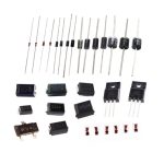
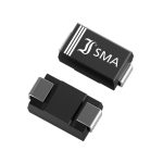
What is a Diode?
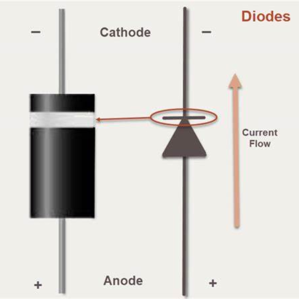
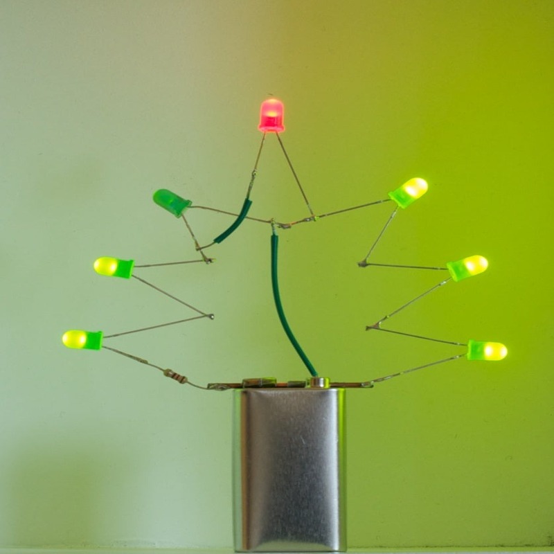
A diode is a small, powerful device crucial in electronics. It controls how current flows through circuits. With two ends, an anode, and a cathode, it’s a one-way gate for electricity. Think of it as a check valve for an electric current, letting it flow in just one direction. This ensures devices function smoothly by directing current the right way.Learn about reverse bias diode, their characteristics, applications, and how to test them.
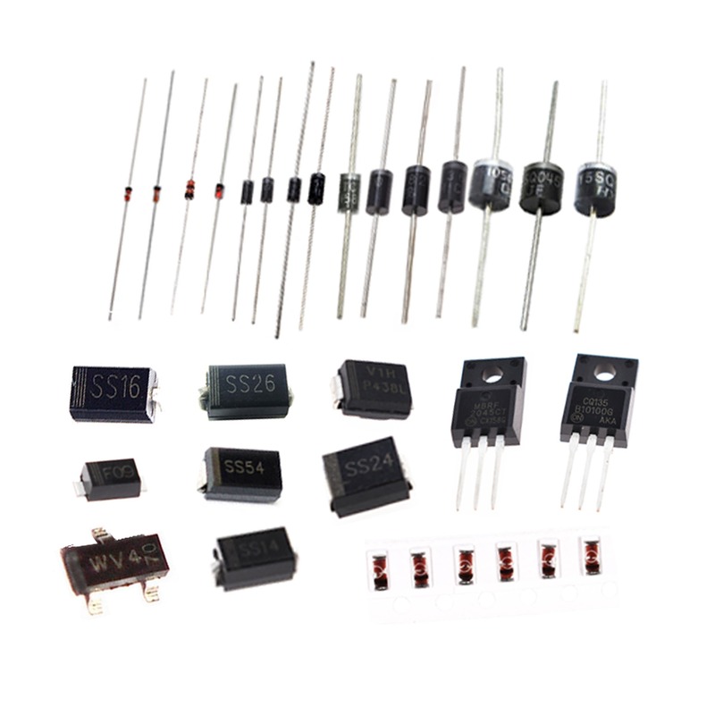
Diodes serve many roles – from converting AC to DC, to regulating voltage, to tuning radios. Different types have different jobs, but at their core, they all manage the flow of current. Their simplicity hides a complex dance of physics that’s essential for modern electronics.
The Concept of Reverse Bias
Understanding the concept of reverse bias is essential for grasping how diodes function. When we talk about reverse biasing a diode, it means applying a voltage across the diode in the opposite direction of its forward conduction. Here’s what’s happening:
- Voltage Application: The positive terminal of the power source is connected to the cathode, while the negative terminal is connected to the anode of the diode.
- Depletion Region Expansion: This voltage application widens the diode’s depletion region, a no-charge zone that naturally exists at the P-N junction.
- Current Flow Hindrance: In a reverse bias condition, the electrical current is significantly inhibited from flowing through the diode due to the enlarged depletion zone.
- Leakage Current: Despite this hindrance, a tiny amount of current, known as leakage current, may flow due to the presence of minority charge carriers.
These factors combine resulting in a state where the diode essentially blocks electrical current, acting more like an insulator than a conductor. It is this property that makes reverse biased diodes so useful in various electronic applications.
Reverse Bias Functionality and Current Flow
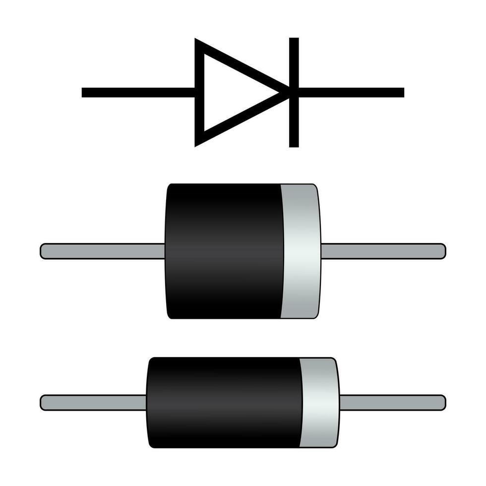
In a reverse bias diode setup, the electrical charge carriers face obstacles. The positive terminal connects to the cathode and the negative to the anode. This setup expands the depletion region, a barrier within the diode. The wider the barrier grows, the harder it becomes for current to pass through. Essentially, the diode acts like an insulator.
Minority carriers can still induce a minimal current, known as leakage current. However, this leakage is usually too small to affect most circuits. It’s a tiny current that’s almost always ignored in reverse bias operations. In essence, reverse bias transforms a diode into a high-resistance pathway that blocks regular current flow.
Impact of Reverse Bias on the Depletion Region
When we reverse bias a diode, it affects the depletion region in two main ways.
Expansion of the Depletion Region
Applying a reverse bias to a diode increases the width of its depletion region.
- The depletion region acts as a barrier in the diode.
- A reverse voltage pushes charge carriers away from the junction.
- This expands the barrier, making it thicker and wider.
- The thicker the depletion region, the less likely charge carriers are to cross.
Electrical Resistance and Insulation
The widened depletion region in reverse bias causes more resistance to current flow.
- The diode behaves like an insulator with very high resistance.
- Since charge carriers can’t cross easily, current flow is effectively blocked.
- This high resistance ensures that no substantial current passes, safeguarding circuits.
In summary, reverse bias dramatically alters the diode’s internal structure. It increases the depletion region’s width and the diode’s resistance to current, turning it into a protective barrier against unwanted current flow.
Reverse Bias Electrical Characteristics and I-V Curve
When a diode is in reverse bias, its electrical characteristics differ significantly from its forward-biased state. Let’s explore these characteristics and what happens on the I-V curve.
Initial Section of the I-V Curve
The I-V curve starts near the origin, showing very little current (near zero). This section highlights the diode’s high resistance under reverse bias.
- The curve lies close to the horizontal axis.
- Displays the small leakage current that barely affects the circuit.
Middle Section of the I-V Curve
As reverse voltage increases, the curve remains flat, emphasizing the stability of the leakage current.
- The diode blocks most of the electric current.
- The flat part of the curve shows consistent high resistance.
Breakdown Region
If reverse voltage continues to rise, the diode reaches a breakdown point. Here, the curve sharply turns upwards.
- The diode starts to conduct significant current despite being reverse biased.
- This is due to avalanche or Zener breakdown, depending on the diode type.
Understanding the Curve’s Significance
This I-V curve is crucial for designing circuits that exploit the diode’s properties.
- Helps in choosing the right diode based on its reverse breakdown voltage.
- Essential for applications where diodes protect against voltage spikes.
Types of Diodes and Their Behavior under Reverse Bias
Different types of diodes respond distinctively when reverse biased.
Zener Diodes
Zener diodes maintain a stable voltage even when reverse biased.
- They allow current upon reaching a certain breakdown voltage.
- This makes them ideal for voltage regulation tasks.
Avalanche Diodes
Avalanche diodes exhibit a controlled breakdown in reverse bias.
- High reverse bias leads to the avalanche effect
- They are useful for protecting circuits against overvoltages.
Photodiodes
Photodiodes generate current when exposed to light, even in reverse bias.
- A widened depletion region improves light sensitivity.
- Mainly used in sensors and solar panels.
Schottky Diodes
Schottky diodes switch quickly between states.
- They have a lower forward voltage drop.
- Their fast switching is crucial in power applications.
Light Emitting Diodes (LEDs)
LEDs operate slightly differently.
- When forward-biased, they emit light, not just heat.
Understanding how these diodes behave under reverse bias aids in selecting the right diode for specific applications and ensuring optimal circuit performance.
Practical Applications of Reverse Biased Diodes
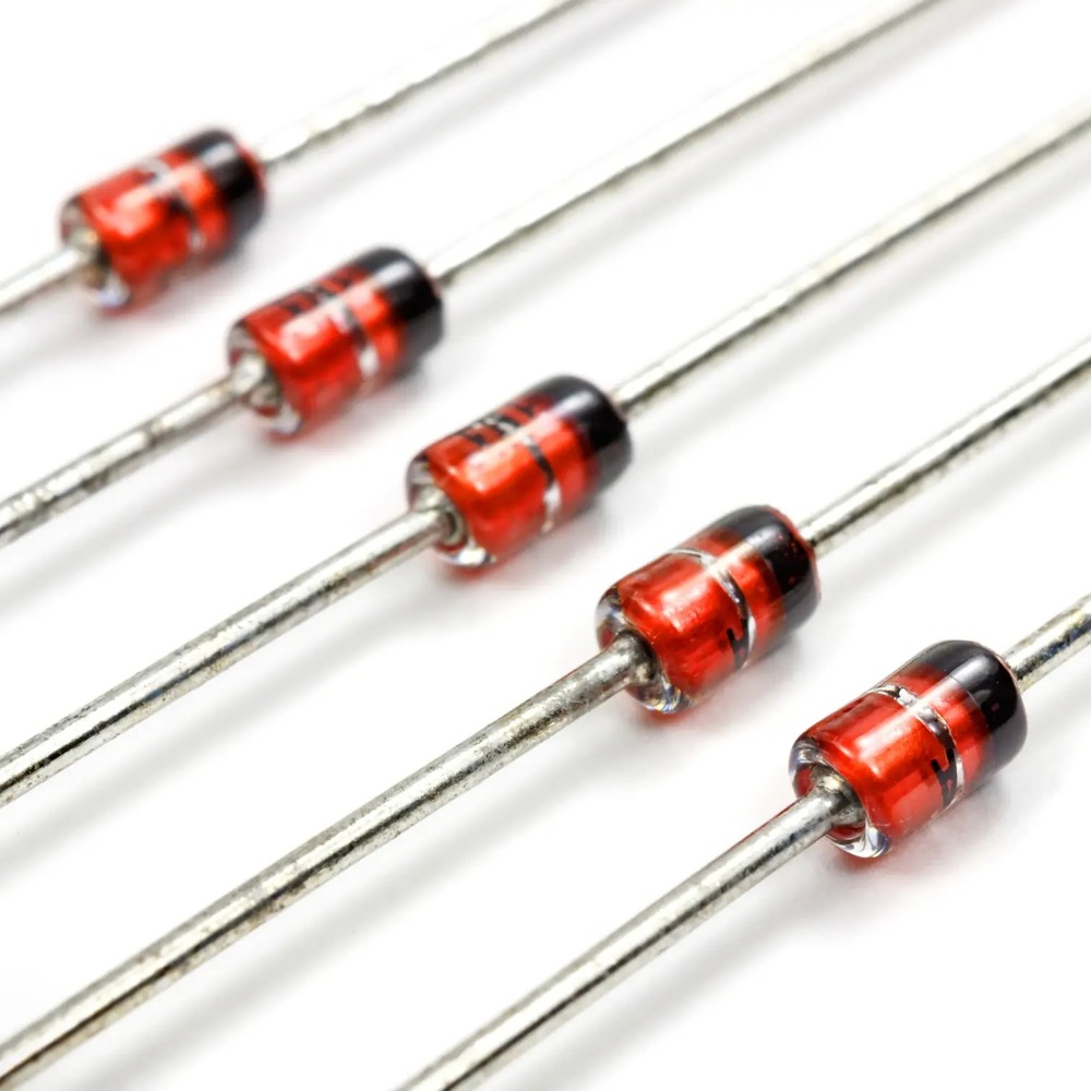
Reverse biased diodes serve several applications in electronics.
Voltage Multiplier Circuits
Voltage multipliers use reverse biased diodes with capacitors.
- They boost input voltage to higher levels.
- Used in high-voltage power supplies and medical imaging.
Protection Circuits
These circuits safeguard sensitive components from damage.
- They prevent reverse current in case of incorrect voltage polarity.
- They clamp voltage spikes to safe levels.
Voltage Clamping
Diodes in reverse bias can limit voltage to a set level.
- They maintain a constant voltage across a circuit.
- Ideal for protecting against voltage transients.
Signal Modulation
Reverse biased diodes are integral in radio frequency modulation.
- They work in mixers and detectors for signal processing.
- Aid in efficient transmission and reception of signals.
Photodiode Sensors
Photodiodes operate in reverse bias to detect light.
- They sense ambient light in cameras and automatic lights.
- Convert light into electric signals in solar panels.
Reverse Biased Diode Applications in Common Devices
Many everyday devices rely on reverse biased diodes.
- Power adapters use them for overcurrent protection.
- Car electronics employ them to manage charge flow.
Comparison of Reverse Bias and Forward Bias
In electronic circuits, diodes can operate in reverse bias or forward bias. Each bias type impacts diode behavior differently.
Diode Response in Forward Bias
When diodes are forward biased, current flows freely. The positive terminal connects to the anode and the negative to the cathode. This aligns with the diode’s natural conduction direction. Electrons move across the junction, allowing current to pass. The depletion region narrows, reducing resistance.
Diode Response in Reverse Bias
Contrastingly, reverse bias restricts current flow. Linking the positive terminal to the cathode increases the depletion region. Current is blocked, except for a minor leakage from minority carriers.
Current Flow and Voltage Drop
Forward bias has a low voltage drop across the diode. This allows for more efficient current flow. On the other hand, reverse bias has almost no current flow. The diode exhibits high resistance.
Applications and Circuit Design
Devices use forward bias for tasks like rectifying current. Reverse bias is for protection against reverse voltage damage. Each bias mode serves a purpose in different circuit designs. Reverse bias is key for protection circuits, while forward bias is crucial in power conversion.
Understanding these differences ensures correct diode use and improves circuit performance. It protects devices from potential harm due to incorrect current flow.
Troubleshooting and Testing Reverse Biased Diodes
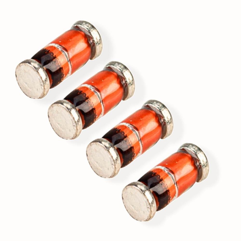
When working with reverse biased diodes, troubleshooting and testing are critical steps. These processes help identify and resolve any issues that might arise during operation. Here are the key factors and methods involved in troubleshooting and testing reverse biased diodes.
Understanding the Importance of Testing
Testing ensures that reverse biased diodes function as intended. It confirms that the diode blocks current in reverse bias and passes minimal leakage current.
Common Troubleshooting Steps
- Initial Visual Inspection: Look for physical damage like cracks or burns on the diode.
- Multimeter Testing: Use a multimeter in diode mode to check for proper operation. Diodes should show high resistance in reverse bias.
- Leakage Current Measurement: Measure the leakage current to confirm it’s within acceptable limits. It should be low under reverse bias.
Diode Testing for Breakdown Voltage
- Gradual Voltage Increase: Apply increasing reverse voltage to the diode.
- Monitor Behavior: Watch for sudden increases in current that indicate breakdown.
- Determine Breakdown Voltage: Identify the voltage at which the diode begins to conduct significantly.
Using an Oscilloscope for Diode Testing
- Set Up Oscilloscope: Connect the diode to observe its response to reverse bias over time.
- Check Waveforms: Ensure the diode does not conduct current until the breakdown voltage is reached.
Recognizing Failures in Diodes
- Short Circuits: A diode that conducts in reverse bias could have an internal short.
- Open Circuits: A diode showing infinite resistance in both directions may be open.
Preventive Measures
- Follow manufacturer guidelines for maximum reverse voltage ratings.
- Avoid exposing diodes to conditions that exceed their specified limits.
In conclusion, careful troubleshooting and testing of reverse biased diodes are essential for reliable electronic designs. These steps help prevent failures and ensure diodes meet their performance criteria.
