Diode Diagram: An In-Depth Guide to Understanding Diodes in Electronics
Introduction
A diode is a semiconductor device that allows electricity to flow in one direction while blocking it in the opposite direction. This characteristic makes diodes critical components in many electronic devices. They are used extensively in power supplies, signal processing, and more.
Diode diagrams provide visual representations of these devices and their connections within circuits. Understanding these diagrams is vital for students, professionals, hobbyists, and educators. Without a clear comprehension of diode diagrams, one may struggle to grasp how diodes influence the functionality of electronic systems.
This article aims to explain diodes, present various types and their corresponding diagrams, and discuss how to interpret these diagrams effectively. Furthermore, we will delve into the characteristics of diodes and their everyday applications. By the end, readers will gain a comprehensive understanding of diode diagrams and their importance in electronics.

Types of Diodes
Diodes come in various types, each designed for specific applications. Here are some common types along with their uses and symbols:
1. Rectifier Diodes
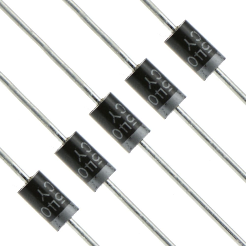
Rectifier diodes are perhaps the most widely recognized type. They convert alternating current (AC) to direct current (DC) by allowing current to flow in one direction only. This function is crucial for power supply circuits.
2. Zener Diodes
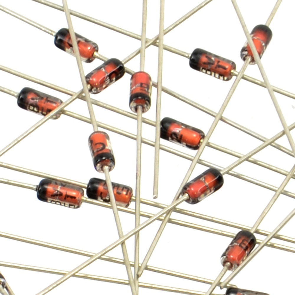
Zener diodes are specialized for voltage regulation. They permit reverse current flow when the voltage exceeds a defined threshold, maintaining a stable output voltage. These diodes are essential for protecting circuits from voltage spikes.
3. Schottky Diodes
Schottky diodes feature a low forward voltage drop and fast switching capabilities. This makes them ideal for high-frequency applications, such as switching power supplies and radio frequency circuits. They can be identified by their unique symbol in diode diagrams.
4. Light Emitting Diodes (LEDs)
Light Emitting Diodes emit light when an electric current passes through them. They are widely used in displays, indicators, and lighting applications due to their energy efficiency and longevity. New designs and colors are constantly being developed, expanding their versatility.
5. Photodiodes
Photodiodes are designed to convert light into electrical current. They operate on the principle of the photoelectric effect and are commonly found in optical communication and sensing applications. Their ability to respond to light makes them suitable for various advanced technologies.
By recognizing these different types of diodes, one can better understand a diode diagram’s significance in various circuits. Each type serves a specific purpose, fulfilling roles that are vital in today’s electronics.
Understanding Diode Diagram
Diode diagram are essential for understanding how diodes function in electronic circuits. These diagrams include symbols and notations that represent various diode types and their connections.
Common Symbols Used in Diode Diagrams
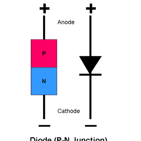
The most basic representation of a diode is a triangle pointing toward a vertical line. The triangle signifies the direction of allowed current flow, while the vertical line indicates the cathode. In some cases, different symbols represent specific types of diodes, such as Zener or Schottky diodes. Recognizing these symbols is essential for interpreting diode diagrams accurately.
How to Read Diode Diagrams Effectively
Reading diode diagrams requires understanding both the symbols and the components around them. Here are a few tips:
1. Identify the Symbols: Begin by identifying the diodes and their types within the diagram. Look for the standard diode symbol and any variations representing different types.
2. Examine the Connections: Observe how the diodes are connected within the circuit. Pay attention to the polarity of each connection, as this will affect current flow.
3. Understand the Circuit Functionality: To interpret the diode’s purpose, consider the overall function of the circuit. Determine where the diode fits in and how it contributes to the circuit’s operation.
By mastering these skills, readers can effectively use diode diagrams to analyze and design circuits more confidently.

Diode Circuit Diagram Examples
Diode circuit diagrams illustrate the practical applications of diodes. Understanding these examples provides insights into how diodes function within various electronic systems.
1. Rectifier Circuit Diagram
A basic rectifier circuit typically consists of a transformer, a rectifier diode, and a load. The transformer steps down AC voltage before the rectifier diode converts it to DC. The diode allows current to pass during the positive half-cycle of the input waveform, resulting in a pulsating DC output.
2. Zener Diode Voltage Regulator Circuit Diagram
In a Zener diode circuit, the Zener is placed in reverse bias across the load resistor. When the input voltage exceeds the Zener breakdown voltage, the Zener diode conducts, maintaining a stable output voltage across the load. This diagram is vital for understanding how diodes can protect sensitive electronic components.
3. LED Circuit Diagram
An LED circuit diagram typically shows a current-limiting resistor in series with the LED. The resistor prevents excessive current from flowing through the LED, ensuring that it operates safely. This type of circuit is prevalent in applications such as indicator lights and displays.
4. Photodiode Circuit Diagram
In a photodiode circuit, the diode is often used in conjunction with an amplifier. Light hitting the photodiode generates a current, which the amplifier processes. This configuration is essential in optical communication systems, showcasing how diodes can function in sensing applications.
Characteristics of Diodes
Understanding the characteristics of diodes is fundamental to their operation. Here are some key characteristics:
1. Forward Bias
In the forward-biased state, the diode allows current to flow when the anode is more positive than the cathode. This promotes conduction and minimizes resistance, enabling the circuit to function effectively.
2. Reverse Bias
When reverse-biased, the diode blocks current flow. However, a small leakage current may still flow until the reverse voltage approaches the breakdown voltage. Understanding the difference between these two states is essential for effective circuit design.
3. Breakdown Voltage
The breakdown voltage is the point at which the diode begins to conduct in reverse bias. Diodes designed for voltage regulation, such as Zener diodes, use this property to maintain a controlled output voltage. It is essential to select diodes with appropriate breakdown voltages for specific applications.
4. IV Characteristics
The current-voltage (IV) characteristic curve of a diode depicts its behavior under different voltage conditions. The curve shows the relationship between current and voltage, providing valuable insights into the diode’s efficiency and response. Analyzing the IV curve is crucial for predicting how a diode will perform in a circuit.
Diode characteristics play a vital role in applications and user considerations. By understanding these properties, individuals can select the right diodes for their specific needs.

Applications of Diodes
Diodes are integral to many electronic applications, serving essential functions in a range of devices.
1. Signal Processing
Diodes play a critical role in signal modulation and demodulation. In communications, they help isolate and process signals, enabling efficient data transmission.
2. Voltage Regulation
Zener diodes maintain stable voltage levels in circuits and are often used in consumer electronics for power management. Their ability to regulate voltage is critical for protecting delicate components.
3. Light Emission
LEDs have revolutionized lighting and display technologies. Their energy efficiency and versatility make them ideal for a wide range of applications, including televisions, smartphones, and general-purpose lighting.
4. Sensing Applications
Photodiodes are used in optical and sensor applications. They help convert light signals into electrical signals for systems that require light detection and signaling.
Diodes have a vast range of applications and are essential to contemporary electronics. Understanding these uses can help individuals appreciate the significance of diode diagrams in various circuits.
Conclusion
In conclusion, a diode diagram is a fundamental component of understanding electronics. Diodes serve essential functions in circuits, enabling devices to operate efficiently. From rectifiers to Zener diodes, each type has unique characteristics and applications that make them suitable for specific tasks.
Mastering how to read diode diagrams allows students, professionals, and hobbyists to better comprehend and design electronic systems. As technology continues to evolve, the necessity for diodes and their diagrams will remain significant.
For anyone venturing into electronics, utilizing diode diagrams is crucial for gaining insights into circuit functionality. By doing so, you enhance your ability to design, troubleshoot, and innovate in the field of electronics. Embrace the knowledge of diodes and their diagrams, and elevate your understanding of electronic systems today!


