Introduction to Diode Polarity
Diodes are crucial components in electronic circuits. They control the direction of current flow, which is essential for the proper functioning of many devices. Understanding diode polarity—knowing which way the current flows through the diode—is vital. Each diode has two terminals: the anode and the cathode. The current within a diode flows from the anode to the cathode, and this is facilitated by the diode’s design that allows current to flow in only one direction. This characteristic is what prevents damage in electronic circuits by ensuring that electricity flows correctly. Recognizing the diode positive and negative sides of a diode ensures that they are correctly installed and functioning as intended.
The Importance of Correct Diode Orientation
Understanding and ensuring correct diode orientation is crucial for multiple reasons. Here are the key points:
- Prevent Damage: Incorrectly oriented diodes can cause short circuits, damaging the diode and connected components. By identifying the diode positive and negative correctly, these risks are minimized.
- Ensure Functionality: Diodes are designed to allow current to flow in a single direction. The correct orientation is necessary for the diode to perform this function effectively.
- Reduce Troubleshooting: Diode misorientation can result in malfunctioning circuits. Recognizing the anode and cathode helps reduce time spent troubleshooting errors in electronic devices.
- Maintain Efficiency: When diodes are oriented correctly, they contribute to the overall efficiency of the circuit. This means the device uses power effectively, leading to energy savings.
- Compliance with Design: Electronic circuit designs assume correct diode placement. To follow the design specifications and ensure the device operates as intended, diode positive and negative must be respected.
It is clear that the right diode placement matters a lot from the perspective of reliability, efficiency, and functionality. Keeping in mind the importance of identifying the diode positive and negative is a basic, yet essential skill for anyone working with electronics.
Visual Identification of Diode Polarity
Visual cues are key for identifying diode positive and negative. Most diodes have physical marks to indicate polarity. Here’s how to recognize them:
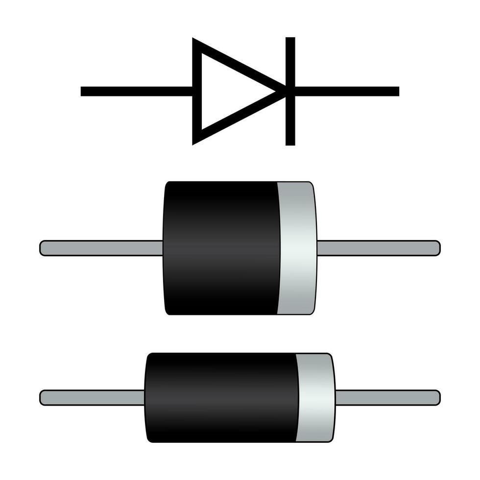
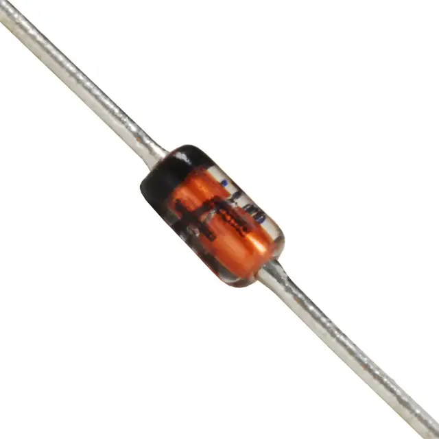
- Striped Band: Look for a stripe or band on one end of the diode. This mark usually signifies the cathode, the negative side. The other end, without the stripe, is the anode or the positive side.
- Color Coding: Some diodes may use color coding to indicate polarity. A specific color on one end can represent the cathode or anode. Refer to manufacturer data for details.
- Terminal Size: In certain diodes, the anode and cathode terminals may differ in size. Often, the cathode terminal is slightly shorter.
- Physical Shape: Some diodes have a tapered shape where the narrower end points to the cathode.
By learning these visual identifiers, you can quickly determine the diode positive and negative without in-depth testing. This is vital when handling multiple components or working under time constraints. Properly identifying diode polarity at a glance can prevent errors during the assembly of electronic circuits and speed up the troubleshooting process. Remember, when in doubt, double-check with a multimeter or refer to the component’s datasheet for clarification.

Understanding Anode and Cathode Terminology
To properly work with diodes, it’s essential to grasp the terms anode and cathode. The anode is the terminal where the current enters a diode. The cathode, on the other hand, is where current exits. Think of the anode as the ‘positive’ side and the cathode as the ‘negative’ side. This terminology stems from early battery technology, and it’s still used in modern electronics to make it clear which way the current should flow.
Anode – The Positive Side
The anode is marked as the positive (+) side. In a correctly functioning circuit, electrons move from the negative side of the power source, through the circuit, and into the anode of the diode. When the diode positive and negative are correctly identified, the anode will align with the positive voltage in your circuit. Remember, diodes are designed to allow current to flow in one direction—from the anode to the cathode. So, identifying the anode is critical for diode positive and negative confirmation.
Cathode – The Negative Side
The cathode is pointed out as the negative (-) side of the diode. It’s typically marked with a stripe or band, as mentioned previously. Current flows out of the diode from the cathode. When installing a diode, make sure that the cathode corresponds to the negative side of your circuit. Incorrect placement where the cathode is on the positive side can result in diode damage and circuit malfunction.
By understanding these terms, you are taking a crucial step in recognizing diode positive and negative. This knowledge will serve as a foundation for correctly implementing diodes in any electronic project. Next time you work with diodes, ensure that you check for the anode and cathode and align them according to your circuit’s needs. This is the best way to avoid common errors and ensure your electronics function as designed.
Using Multimeters to Determine Diode Polarity
When visual cues are insufficient, a multimeter becomes an invaluable tool for identifying diode positive and negative. Multimeters can measure many aspects of electrical components but are particularly useful for testing diode polarity.
Here are simple steps to use a multimeter to determine diode polarity:
- Set the Multimeter: Switch your multimeter to the diode symbol, which usually displays as a triangle with a line across one corner.
- Test Leads: Connect the multimeter’s test leads to the diode. The red lead is positive, and the black lead is negative.
- Reading the Results: If the diode is functioning and correctly oriented, the multimeter will show a voltage drop between 0.5V to 0.8V when the red lead is touching the anode and the black the cathode. A reverse connection will show ‘OL’ (overload), indicating no current flow.
- Confirmation: A correct reading confirms which side is the anode (positive) and which is the cathode (negative).
It’s important to note that while testing diodes using a multimeter, ensuring the testing is done on a de-energized circuit is critical for safety and accuracy. Additionally, a lack of reading in both directions may suggest diode failure. In such cases, replace the diode before proceeding with your project.
Using a multimeter not only helps confirm diode polarity but also provides a practical method for testing overall diode functionality. Always remember to handle multimeters with care and follow the manufacturer’s instructions to achieve accurate results.

Diode Polarity Symbols in Circuit Diagrams
In circuit diagrams, diode polarity is marked with specific symbols that are essential for interpreting the design and connecting components accurately. Recognizing these symbols is critical for anyone working with electronics, particularly when assembling or repairing circuits. Here’s how to identify diode polarity symbols in circuit diagrams:
- Triangle with a Line: The most common symbol for a diode in a circuit diagram is a triangle pointing towards a line. The triangle represents the anode, which is the positive side, while the line indicates the cathode, the negative side.
- Arrow Notation: Sometimes, an arrow is used instead of a triangle. The direction of the arrow indicates the allowable current flow – from the tail (anode) to the head (cathode).
- Plus and Minus Signs: Some diagrams may include a ‘+’ or ‘-’ sign next to the diode symbol. This explicitly marks the anode (positive) and cathode (negative), respectively.
- Letter Representation: Occasionally, letters ‘A’ for anode and ‘K’ for cathode are placed beside the respective ends of the diode symbol to denote polarity.
Understanding these symbols helps prevent errors during the installation of diodes and ensures that electronic devices operate according to their design specifications. Always double-check the symbols against the device’s documentation to ensure correct interpretation.
Common Mistakes When Identifying Diode Polarity
Identifying diode positive and negative is usually straightforward, but mistakes can occur frequently, especially for beginners. These errors can lead to malfunctions or damage in electronic circuits. Here are some common pitfalls to avoid when determining diode polarity:
- Misinterpreting Visual Indicators: Sometimes, the colored band or marking on a diode can be confused for the anode. It’s essential to remember that this usually signifies the cathode, the negative side.
- Assuming Terminal Size as an Indicator: Not all diodes have differing terminal sizes. Depending on a size difference without confirming can lead to incorrect assumptions.
- Ignoring Circuit Diagrams: Skipping the circuit diagram’s diode symbols can cause reverse installation. Paying careful attention to the schematic prevents this error.
- Improper Multimeter Use: Setting the multimeter incorrectly or reversing the test leads can result in false readings. It’s important to double-check the settings and lead placements.
- Forgetting to Check Device Documentation: Manufacturer data sheets contain specific information about diode polarity. Overlooking these can lead to mistakes in identifying the anode and cathode.
By avoiding these common mistakes and applying the knowledge from previous sections on visual cues, terminology, multimeter use, and circuit symbols, you’ll be more likely to identify diode positive and negative correctly. Keep practicing and referring back to reliable resources to solidify your understanding of diode polarity.

Practical Tips for Working with Diodes in Electronics
Working with diodes requires careful attention to detail and a clear understanding of polarity. To avoid common mistakes and ensure successful installation or repair of electronic circuits, here are some practical tips:
- Double-Check Polarity: Before soldering diodes into place, double-check their polarity. Use the visual indicators or a multimeter as a second confirmation.
- Mind the Heat: Soldering can damage diodes if exposed to high temperatures for too long. Use a heat sink or be quick with the soldering iron to protect the diode.
- Organize Components: Keep anodes and cathodes of different diodes separate. This prevents confusion and potential errors when picking up parts for a project.
- Use Correct Tools: Employ the right tools, like tweezers or specialized pick-up tools, to handle small diodes. This helps maintain their integrity and avoids accidental reversals.
- Follow Manufacturer Guidelines: Always read manufacturer guidelines and datasheets. They provide the most accurate information on diode polarity and specifications.
- Test Before Finalizing: Before finalizing your circuit, test the diodes’ functionality with a multimeter. This can save time on troubleshooting later on.
- Maintain a Clean Workspace: A clean and organized workspace reduces the risk of losing track of where diodes are placed within the circuit, potentially leading to polarity errors.
- Label Everything: If you’re pausing your project, label the diode’s orientation. This helps you remember their correct placement when you resume work.
- Continual Learning: Stay informed about new diode types and their polarity indicators. Technology evolves, and so should your knowledge.
By keeping these tips in mind and applying them to your work with diodes in electronics, you enhance the likelihood of a smooth and trouble-free experience. Remembering diode positive and negative is essential, but so is a methodical and informed approach to your electronic projects.


