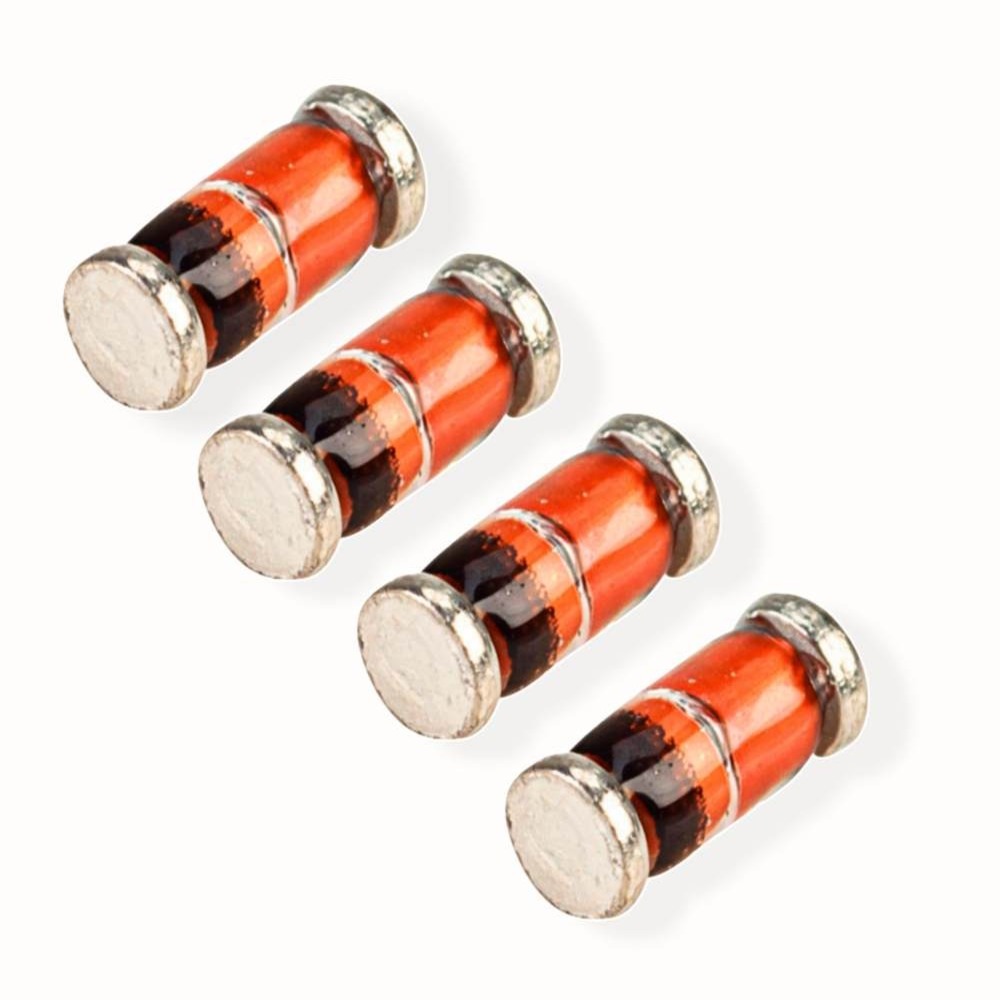
Introduction to Diode Fundamentals
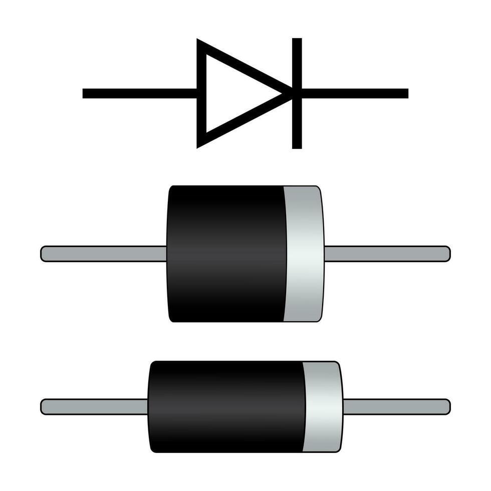
Diodes are integral components in electronic circuits, acting as directional gates for current flow. Understanding the fundamentals of diode operation is essential for anyone delving into electronics. Diodes come with two terminals, an anode, and a cathode, and they function by allowing current to flow in one direction while blocking it in the opposite. This behavior makes them useful for a variety of applications ranging from rectification, where they convert alternating current (AC) to direct current (DC), to voltage regulation and protection against reverse current in diode circuit.
Diodes are not just simple on-off switches but have complex behaviors that depend on their biasing, which is the direction and magnitude of the voltage applied across them. By manipulating this biasing, electronic engineers can harness diodes for different functions in circuits. The way diodes are biased will greatly affect their operation, and it can be categorized mainly into two types—forward bias and reverse bias—each with its distinct characteristics and implications for circuit design.
In forward biasing, the diode acts almost like a closed switch, allowing current to flow through it. This occurs when the voltage at the anode is higher than at the cathode. On the flip side, reverse biasing happens when the voltage at the cathode is more positive than the anode, causing the diode to act as an open switch and preventing current flow.
One cannot overlook the significance of choosing the correct diode for specific applications. Factors such as the material the diode is made from, like silicon or germanium, and its particular type, such as Zener, Schottky, or rectifier diodes, are crucial in determining the diode’s properties and suitability for specific tasks within electronic circuits. In the subsequent sections, we will delve deeper into the various types of diode biasing and their applications in electronics.
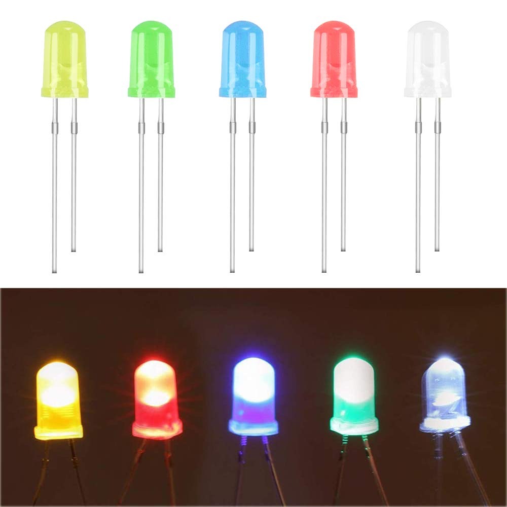
Types of Diode Biasing
Understanding how diodes are biased is key to using them effectively in electronic circuits. Biasing refers to the way voltage is applied to a diode, directly influencing its conductive state. Let’s look at the two primary types of diode biasing: forward bias and reverse bias.
Forward Biased Diodes
In forward bias, the anode receives a higher voltage than the cathode. This decreases the diode’s resistance to a minimal level, allowing current to flow through it, analogous to a closed switch. For a silicon diode, this typically occurs at a threshold voltage, often around 0.7 volts, known as the knee voltage.
Reverse Biased Diodes
Conversely, reverse bias occurs when the cathode is at a higher voltage than the anode. This condition increases the diode’s resistance greatly, preventing the flow of current as if it were an open switch. If reverse voltage exceeds a specific limit, known as the breakdown voltage, the diode can conduct, often leading to damage if not designed for such conditions like a Zener diode.
Diode Applications in Electronics
Diodes are versatile components used in various electronic applications. We will explore their functions in rectification, voltage regulation, signal limiting, and wave shaping.
Rectification of AC to DC
Diodes play a crucial role in converting alternating current (AC) into direct current (DC). This process, known as rectification, relies on diodes to selectively allow current flow during positive cycles while blocking it during negative cycles. This action results in a pulsating DC that is later smoothed into stable DC for use in electronic devices.
Voltage Regulation with Zener Diodes
Zener diodes are engineered to operate in reverse bias. They stabilize voltage by allowing current to flow in reverse once the applied voltage exceeds the diode’s Zener breakdown voltage. This feature is essential for maintaining a consistent voltage level in electronic circuits, making Zener diodes vital for protecting sensitive components.
Signal Limiting and Clipping
Diodes can also protect circuits from voltage spikes. They ‘clip’ the voltage to a predetermined level, limiting the signal to a range that is safe for the rest of the circuit. This function is especially critical in communication systems where signal integrity is paramount.
Wave Shaping and Clamping
In electronic signal processing, diodes help in shaping waveform outputs. Clamping circuits employ diodes to shift the level of a waveform without altering its shape, typically to accommodate other circuitry in digital systems. Meanwhile, wave shaping enables creating desired patterns from input signals, useful in timing and control applications.
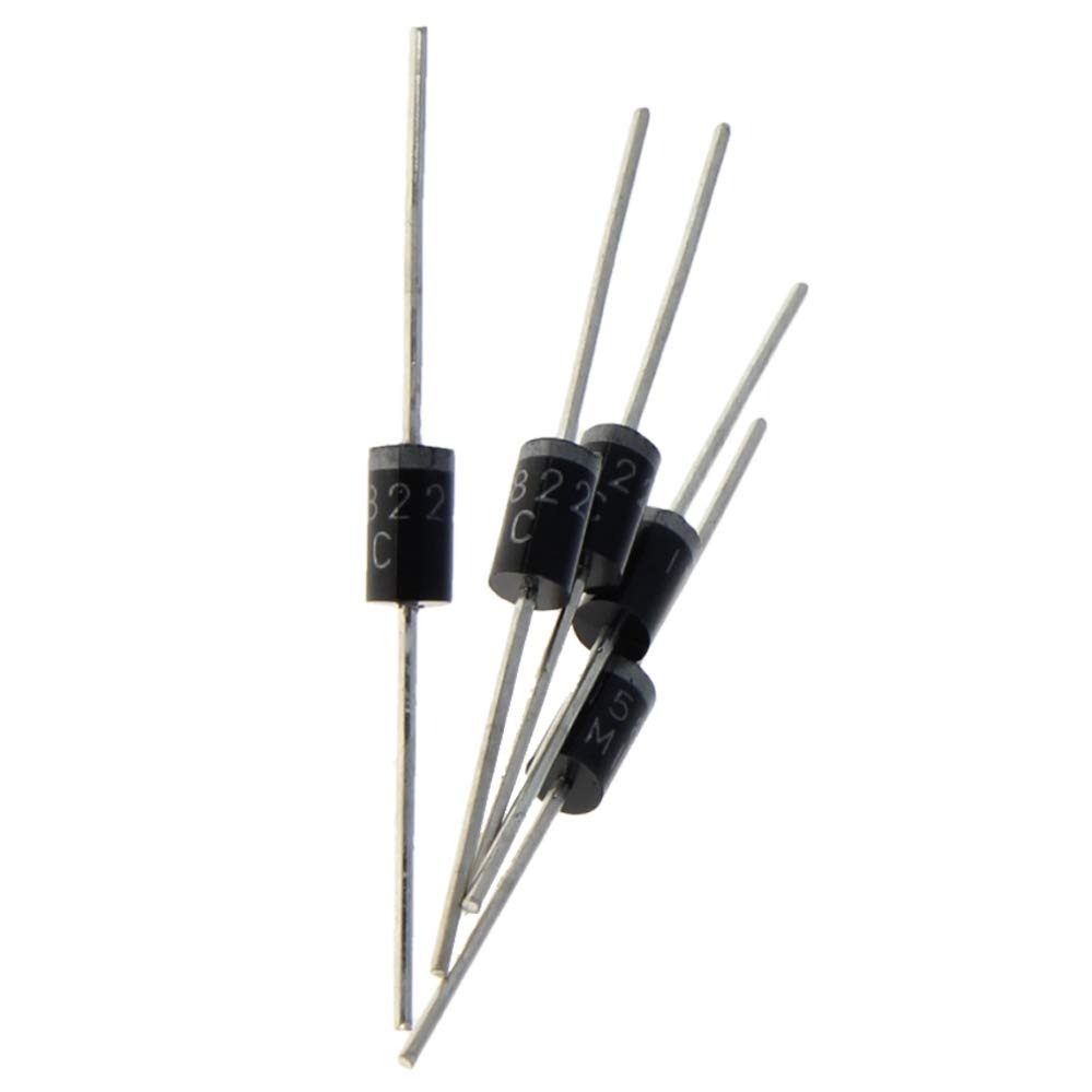
Analyzing Diode Circuit Models
To effectively utilize diodes in electronic circuits, it’s essential to understand how they behave under different conditions. This involves analyzing diode circuit models to predict their performance in real-world applications. Two models are commonly used: simplified models and comparisons between real and ideal diodes.
Simplified Diode Models
Simplified diode models help us predict the behavior of diodes in a circuit without delving into complex calculations. The three most common approximations are:
- First Approximation: Treats the diode as an on-off switch, where forward bias is ‘on’, and reverse bias is ‘off’.
- Second Approximation: Adds the knee voltage, typically 0.7V for silicon diodes, which represents the voltage needed to start the current flow in forward bias.
- Third Approximation: Incorporates the diode’s bulk resistance, providing a more precise voltage-current relationship for diodes under bias.
These models simplify analysis, enabling quicker assessments of diode circuits without compromising too much on accuracy.
Real Diode vs Ideal Diode
While ideal diodes are perfect switches with no resistance or voltage drop, real diodes exhibit a small voltage drop and resistance when conducting. They also have a limit to the reverse voltage they can withstand before breaking down. Understanding these characteristics is pivotal for electronic circuit design, ensuring that the diodes are neither over-stressed nor fall short of their required function in a given circuit.
In summary, diode circuit models are invaluable for predicting diode behavior, while a grasp of real versus ideal diode characteristics informs appropriate diode selection and application in electronic designs.
Special Purpose Diodes and Their Uses
Diodes are not all the same. Some are made for special jobs in electronic circuits. Let’s talk about a few of these special diodes and what they do.
Schottky Diodes
Schottky diodes are very fast. They switch on and off quicker than most other diodes. This makes them perfect for high-speed circuits. They have a low turn-on voltage, around 0.2 to 0.3 volts. Because of this, they are good for power applications too. You will find them in power supplies and radio frequency devices.
Germanium Diodes
Germanium diodes are known for their low turn-on voltage. It is about 0.3 volts, less than silicon diodes. This low voltage drop is good for detecting small signals. It’s why they are used in radio and audio systems for signal detection.
Junction Diodes
Junction diodes are the most common type of diodes. They are used for many different tasks. For example, they can control the direction of current in a circuit. They do not work the same in both directions like a resistor does. This unidirectional action is their main feature. Junction diodes are the basic building blocks for many diode applications.
Practical Considerations for Diode Circuit Design
Navigating through diode circuit design involves several practical factors. In the following sections, we’ll cover the crucial aspects of selecting the appropriate diode, understanding its specifications, and ensuring adequate protection within circuits.
Selecting the Right Diode
Choosing a diode is critical for your circuit’s success. Start by identifying the purpose of the diode in your circuit. Consider the current and voltage requirements, switch response times, and any specific attributes like low turn-on voltage. For high-speed switching, opt for Schottky diodes. For signal detection, germanium diodes could be better due to their low voltage drop.
Understanding Diode Specifications
Diode specs detail its performance limits. Key specs include maximum forward current (If), peak inverse voltage (PIV), forward voltage drop (Vf), and power dissipation. Match these ratings with your circuit’s demands to ensure the diode can handle its intended use without failing.
Diode Protection in Circuits
Diodes can fail if exposed to conditions beyond their limits. To protect them, incorporate current-limiting resistors to prevent excessive current flow. Use heat sinks to dissipate thermal energy in power applications. For voltage spikes, consider using transient voltage suppression diodes. Always check the diode’s reverse breakdown voltage to prevent irreversible damage due to high reverse bias.
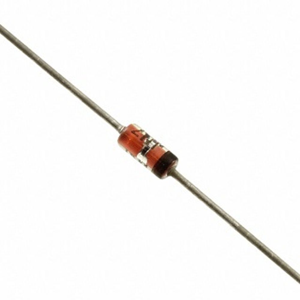
Solving Complex Diode Circuits
In the realm of electronics, working with complex diode circuits is a common challenge. To navigate this complexity, a clear understanding of certain fundamental principles is paramount. This section provides insights into key techniques and methodologies for analyzing and solving diode circuit problems. These include Kirchhoff’s laws, the use of diode approximations, and strategies for addressing configurations that involve multiple diodes.
Using Kirchhoff’s Laws
Kirchhoff’s laws, which encompass Kirchhoff’s Current Law (KCL) and Kirchhoff’s Voltage Law (KVL), are vital tools in circuit analysis. KCL states that the total current entering a junction must equal the total current leaving it. KVL asserts that the sum of voltage drops in a closed loop equals the total voltage supplied. Together, they allow for the methodical calculation of unknown values in diode circuits, ensuring all currents and voltages are accounted for accurately.
Diode Approximations
To simplify the analysis of diode circuits, engineers often use diode approximations. This includes the first approximation, which views the diode as a switch, the second approximation, which introduces the knee voltage, and the third approximation, which includes the diode’s bulk resistance. Applying these can streamline the process of solving for current and voltage in a circuit, making it more manageable to predict diode behavior.
Handling Multiple Diode Configurations
When circuits feature multiple diodes, each one must be examined to determine if it’s forward biased or reverse biased based on the applied voltage. By doing so, you can designate each diode as an open or closed switch accordingly. Employing this approach, coupled with Kirchhoff’s laws, users can solve complex configurations step by step. It is crucial to consider how each diode influences the circuit, especially when diodes are arranged in series or parallel, as they can affect the total resistance and voltage pathways.
