Introduction to Diode Testing
Diode testing is crucial for ensuring semiconductor devices function correctly. This guide will explain why testing diodes is essential and how it can prevent future electronic failures. We’ll also cover the specific tools needed for this task, focusing on the use of a multimeter set to diode test mode.
Key Concepts and Importance of Testing Diodes
Diodes control the flow of current, only allowing it in one direction. Testing them helps ensure they operate as intended, which is vital for the reliability of electronic circuits. Faulty diodes can lead to malfunctions or complete failure of electronic systems. Regular testing identifies these issues early, saving time and costs in maintenance.
Tools Needed: Multimeter with Diode Test Mode
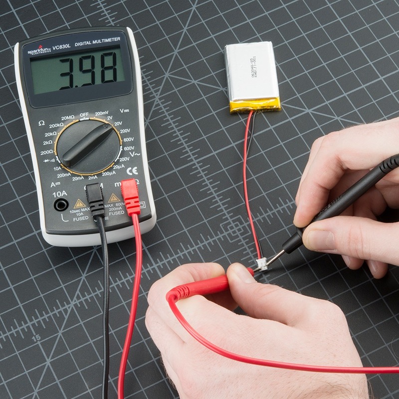
To test diodes effectively, you need a reliable tool. A digital multimeter with a diode setting is essential. The diode setting on the multimeter allows you to check if the diode is permitting current correctly without removing it from the circuit. This setting simplifies the testing process and provides immediate results, making it an indispensable tool for both professionals and hobbyists in electronics. A digital multimeter with a diode setting is crucial for testing components like a flywheel diode. It ensures proper functionality and simplifies diagnostics in electronic circuits.
Step-by-Step Guide to Testing Diodes
Setting the Multimeter to Diode Test Mode
Testing diodes starts with the proper setup of your multimeter. First, make sure the multimeter is off. Then, select the diode setting on the multimeter. This setting often shares a space on the dial with another function but is marked with a diode symbol or a voltage drop symbol. Familiarize yourself with this mode as it specifically caters to diode testing, ensuring accuracy and ease. Turn on the multimeter and proceed to identify the diode leads.
Identifying Diode Leads: Anode and Cathode
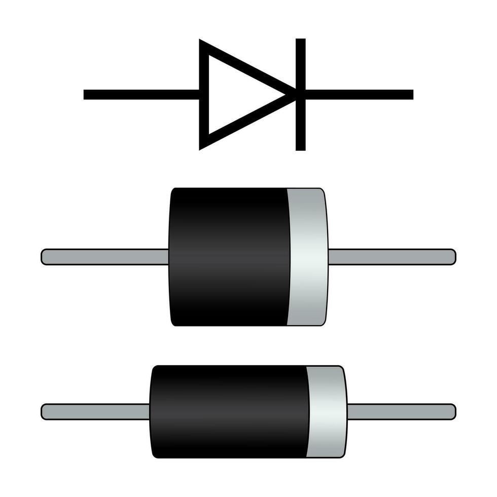
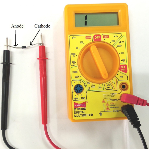
Next, identify the two leads of the diode: the anode and the cathode. The anode is the positive lead, while the cathode is negative. Typically, the cathode is marked with a band or is a different color than the anode. Recognizing these leads is crucial as it determines how you conduct the forward and reverse bias tests. A proper lead identification guarantees you a precise diagnosis of the diode’s health.
Forward Bias Test
Performing the Forward Bias Test
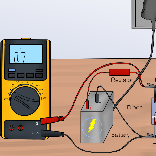
Once your multimeter is set to the diode setting, perform the forward bias test. Start by turning off all power to the circuit and ensuring no voltage exists at the diode; this may require discharging any capacitors. Connect the red (positive) multimeter probe to the anode and the black (negative) probe to the cathode. The multimeter will apply a small voltage to the diode and measure the voltage drop. To test a diode array, set your multimeter to the diode setting. Ensure the power is off, then measure each diode’s forward bias as described.
Analyzing the Results of Forward Bias
In a properly functioning silicon diode, expect a voltage drop between 0.5 to 0.8 volts, indicating current is flowing in the correct direction. If the multimeter reads much lower or higher, it may suggest that the diode is faulty. Consistently, a reading near 0 V could mean a shorted diode, whereas a much higher reading often points to an open diode. Always compare measurements with normal values for the specific diode type being tested. If the diode is germanium, the normal voltage drop ranges between 0.2 to 0.3 V. Accurate analysis helps you determine the diode’s health and ensures the reliability of your electronic circuits.
Reverse Bias Test
After you have completed the forward bias test, it’s crucial to assess the diode in reverse bias to ensure it’s only allowing current in one direction. This reverse check is key for its function in a circuit.
Conducting the Reverse Bias Test
To test the reverse bias, make sure you’ve disconnected the diode from any power source. Reverse the placement of the probes by attaching the red (positive) probe to the cathode and the black (negative) probe to the anode. Your multimeter will indicate if current is mistakenly passing through the diode in the wrong direction. Remember, in this state, a functioning diode should not permit current to flow.
Interpreting the Results of Reverse Bias
A correctly operating diode will show ‘OL’, or overload, on the multimeter in reverse bias, suggesting high resistance and no current flow. If you discover a voltage drop similar to the forward bias test, the diode might be faulty, letting current through both ways. Replace diodes that fail this crucial test to prevent potential damage to your circuit. Interpret these results carefully to preserve the integrity of your electronic systems. When testing a diode, ensure the cathode and anode orientation is correct. A faulty diode can conduct in both directions, compromising circuit integrity.
Common Issues and Troubleshooting
Diode testing using a multimeter can sometimes be tricky. Understanding potential issues helps ensure effective troubleshooting.
Identifying Faulty Diodes
Detecting faulty diodes is a critical aspect of ensuring electronic devices operate reliably. To identify a faulty diode, look for these signs:
- Inconsistent Voltage Readings: If the forward bias test shows substantially different results from expected values (typically 0.5 to 0.8 volts for silicon diodes), it could suggest a problem.
- No Voltage Drop in Forward Bias: A voltage drop close to 0 volts may indicate a shorted diode, while a higher-than-normal drop might suggest an open diode.
- Conductivity in Reverse Bias: During the reverse bias test, a good diode should show ‘OL’ or indicate high resistance, meaning no current flow. If the multimeter shows a voltage drop similar to the forward bias test, the diode might be damaged and conducting in both directions.
Tips for Accurate Measurements
For precise and reliable diode testing with a multimeter, consider these tips:
- Ensure Proper Setting: Always confirm that your multimeter is set to the proper diode setting before beginning tests.
- Maintain Good Probe Contact: Ensure that the multimeter probes make secure contact with the diode leads. Poor contact can result in inaccurate readings.
- Use Known Good Diodes for Comparison: Compare your readings with those taken from a known good diode. This comparison can help confirm the accuracy of your results.
- Check for External Influence: Be mindful of other components in the circuit that might influence the reading. Isolating the diode, when possible, can provide a more accurate measurement.
Advanced Diode Testing Techniques
Enhance your diode testing skills with these advanced techniques.
Testing Diodes in a Circuit
Sometimes, you can’t remove diodes from their circuits for testing. Use the diode setting on your multimeter to measure the diode in the circuit itself. This process, however, might show results influenced by adjacent components. It’s crucial to consider these elements when interpreting your readings.
Comparing with Standard Values
After testing, always compare the diode’s behavior with known good diodes. Each diode type has standard forward and reverse bias values. If the values align well with standards, your diode likely operates correctly. If not, further investigation or replacement may be necessary. Consult the diode’s datasheet for precise standard values to ensure accuracy in your comparisons.
Conclusion
Summary of Diode Testing Process
To test diodes using a multimeter, follow these steps:
- Set the multimeter to the diode testing mode.
- Identify the anode and cathode of the diode.
- Conduct forward bias and reverse bias tests.
- Analyze the voltage drops and resistance readings.
- Compare the results with standard values for typical diodes.
This method ensures efficient and accurate testing, crucial for maintaining electronic devices.
Importance of Regular Diode Checks in Electronic Maintenance
Regular testing of diodes is essential for preventing failures in electronic systems. Faulty diodes can result in malfunctions, leading to costly repairs or replacements. By conducting routine checks, you can identify issues early and ensure your devices operate reliably. This proactive approach saves time and money and maintains the efficiency of electronic systems.


