Introduction to Diode Testing with Multimeters
The ability to test a diode with a multimeter is a fundamental skill for anyone working with electronic circuits. Diodes are components that allow current to flow in one direction, functioning much like a one-way valve in plumbing systems. This characteristic makes them essential in controlling the flow of electrical current in various devices. Multimeters are versatile tools that can perform numerous functions, including diode testing, which is crucial for diagnosing and troubleshooting circuits. Testing diodes with a multimeter involves measuring the voltage drop across the diode in forward bias, as well as checking for high resistance or ‘open’ status in reverse bias.
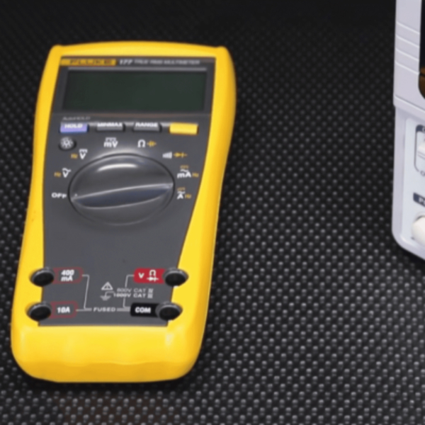
In this guide, we will cover the basics of diode testing, from identifying the anode and cathode to interpreting the results accurately. Whether you’re a seasoned technician or a hobbyist starting out, understanding how to effectively test diodes with a multimeter is an invaluable competence. Let’s begin by exploring the types of diodes and how to adjust your multimeter settings for accurate testing. When testing a flywheel diode, it’s crucial to identify its anode and cathode correctly. This ensures accurate readings and proper functionality in your circuit.
Identifying Diode Types and Multimeter Settings
Identifying Anode and Cathode of Diodes
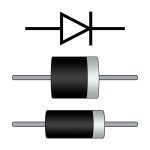
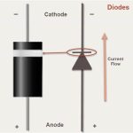
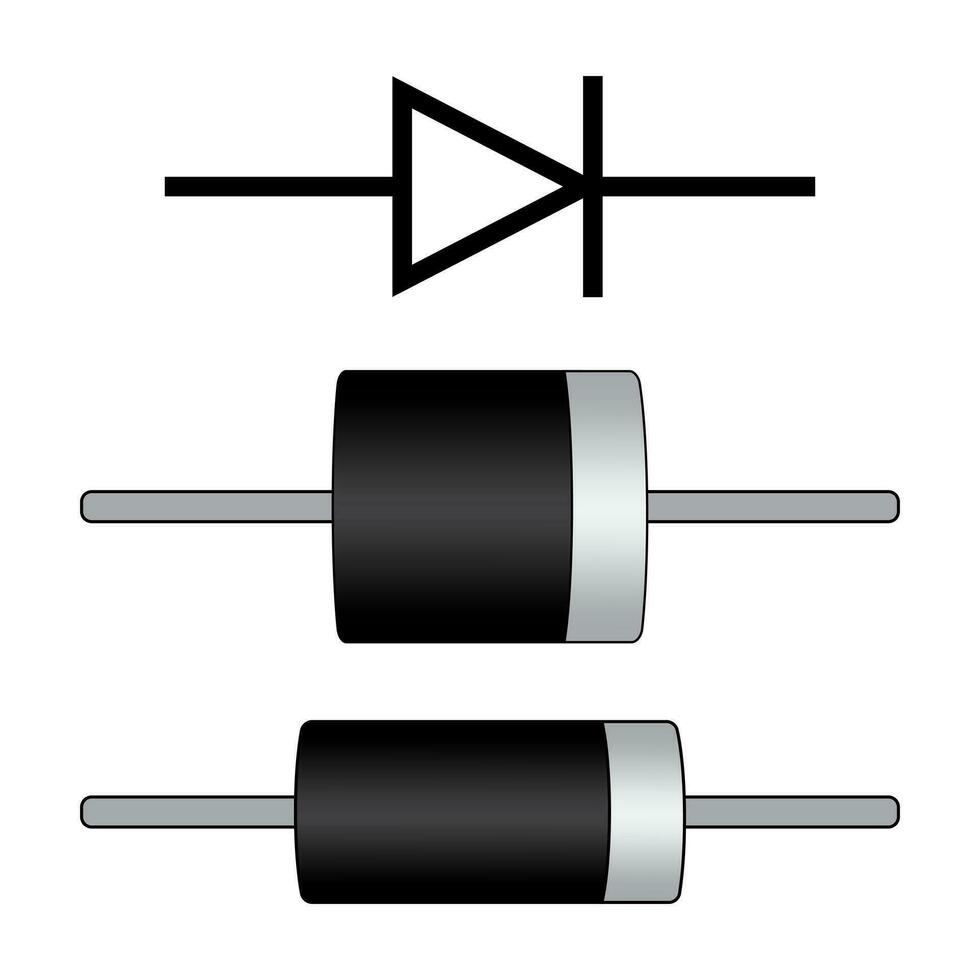
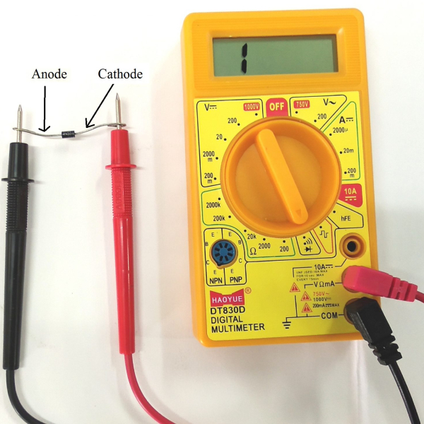
Before attempting to test diode with multimeter, it’s important to identify the two leads of a diode – the anode and cathode. The anode is the positive lead, while the cathode is the negative one. Often, the cathode is marked with a stripe or band. Recognizing these leads accurately is crucial for the testing process, ensuring that you connect your multimeter probes correctly.
Setting Multimeter to Diode Test Mode
Once you’ve identified the anode and cathode, the next step is to prepare your multimeter. Set it to Diode Test Mode for testing diodes. This setting might share a space on the dial with another feature. Look for a diode symbol or refer to your multimeter’s manual if you’re unsure. This mode provides the right conditions for testing diodes effectively, giving clear indications of their state based on the voltage drop and resistance readings. Remember, correct multimeter settings are key to reliable test results. To perform an alternator diode test, ensure your multimeter is set to Diode Test Mode for accurate readings. This will help you effectively assess the diodes’ functionality.
Step-by-Step Procedure for Testing Diodes in Forward Bias
Testing diodes in forward bias with a multimeter allows you to verify their functionality. Here’s a simple step-by-step procedure to follow:
Connecting and Measuring Forward Biased Diodes
- Ensure Safety: First, make sure the power to the circuit is off. Look out for any charged capacitors that might still hold voltage. Discharge them if necessary.
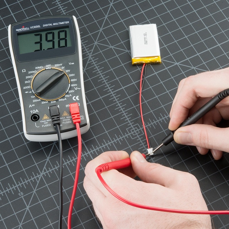
- Set Multimeter: Turn your multimeter dial to the Diode Test Mode. The symbol for this mode usually resembles an arrow striking a line.
- Identify Leads: Find the anode (positive) and cathode (negative) leads of the diode. The cathode is typically marked with a stripe.
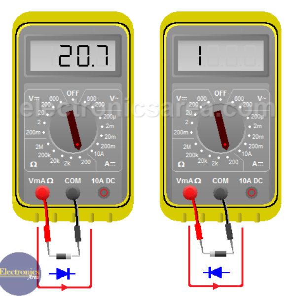
- Connect Probes: Place the red probe on the anode and the black probe on the cathode.
- Record Reading: Observe and note the voltage reading on the multimeter. It should display a drop if the diode is functioning.
Carrying out these steps should allow you to test a diode with multimeter accurately in forward bias, giving you insight into its health and capability.
Reading and Interpreting Forward Bias Test Results
After conducting the forward bias test using a multimeter, the results you obtain are crucial for assessing the health of the diode. Here is how to interpret the readings from the multimeter:
- Voltage Drop: For silicon diodes, a typical reading should show a voltage drop between 0.5 to 0.8 volts. This indicates that the diode is allowing current to flow in the forward direction and is functioning properly. If the reading falls within this range, your diode is likely in good working condition.
- No Voltage Drop: If there is no voltage drop, or the multimeter displays ‘0’, this means that no current is passing through the diode in the forward direction. This signifies an open diode, which is a common sign of failure.
- High Voltage Drop: A reading that is significantly higher than the expected range can suggest that there is a problem with the diode. It might be allowing too much current to pass through or is partially damaged.
It is essential to understand that these readings can vary slightly depending on the specific characteristics of the diode being tested. Germanium diodes have a lower voltage drop—usually around 0.2 to 0.3 volts. Always consult the diode’s datasheet for exact specifications.
When testing diodes, using a multimeter set to Diode Test Mode provides an accurate and reliable method for evaluation. Additional checks, such as testing in reverse bias, can further confirm the diode’s condition. Proper interpretation of the multimeter readings in forward bias is the first step in ensuring the diode’s performance and safety in its application. Remember, accuracy in testing leads to confidence in your electronic circuits. When evaluating a diode array, utilizing a multimeter in Diode Test Mode ensures accurate readings. Reverse bias tests can further validate the overall reliability of the array’s performance.
Step-by-Step Procedure for Testing Diodes in Reverse Bias
To test a diode in reverse bias, follow this straightforward procedure:
Connecting and Measuring Reverse Biased Diodes
- Check For Safety: Before starting, ensure no power is in the circuit.
- Prepare Multimeter: Set your multimeter to Diode Test Mode again.
- Reverse Leads: Connect the red probe to the cathode and the black to the anode.
- Observe Reading: The multimeter should show ‘OL’ or another high-resistance indication.
- Note Results: Write down the reading for comparison and analysis.
This process helps determine if the diode blocks current in the opposite direction, as it should.
Reading and Interpreting Reverse Bias Test Results
After you’ve tested the diode in forward bias, the next crucial step is reverse bias testing. This verifies if the diode effectively blocks current flow in the opposite direction—a hallmark of a properly functioning diode. Interpreting the readings from a reverse bias test is straightforward, but vitally important.
What Does an ‘OL’ Reading Signify?
In reverse bias, a good diode should show a high resistance or ‘OL’ (open loop) reading on your multimeter. This result indicates that the diode is blocking current, as it’s designed to do. If your multimeter shows ‘OL’, you can confirm that the diode is in good health.
Signs of a Faulty Diode in Reverse Bias
If the multimeter displays a voltage drop similar to the forward bias test, it suggests a fault. A diode that allows current to pass in reverse bias is likely either damaged or defective. Such a diode won’t serve its purpose and needs replacement.
Consistency Across Both Tests
For full confidence in the diode’s functionality, the results from both forward and reverse bias tests should be consistent with the diode’s specifications. A good diode shows a voltage drop in forward bias and high resistance in reverse bias. Any deviation from this pattern suggests a problem that warrants further investigation.
Proper interpretation of multimeter readings in reverse bias testing is just as crucial as the forward bias test. Understanding these results helps maintain the integrity of your electronic circuits and prevents potential malfunctions. Always treat testing results with care and consider re-testing if the results are unexpected or unclear.
Additional Tips for Accurate Diode Testing
Testing diodes with a multimeter requires careful attention to detail for accuracy. Here are additional tips to ensure that each diode test you perform gives reliable results:
Importance of Removing Diode from Circuit
To get a clear and accurate reading, it is often essential to remove the diode from the circuit. This prevents other circuit elements from interfering with the true diode behavior. Take precautions while desoldering to avoid damage.
Comparing with Known Good Diodes
To confirm the accuracy of your multimeter readings, compare them with those from a known good diode. This comparison can catch errors and give confidence in your testing process. This step is particularly useful when you are unsure about the correct values to expect.


