Introduction to Diodes and Their Symbols
Diodes are key ingredients in electronic circuits. They’re like traffic controllers for electric current, making sure it flows in just one direction. Understanding how to read their symbols is crucial for any budding electronics enthusiast or experienced engineer alike.Understanding diode schematics is essential for ensuring proper current flow and preventing circuit issues in electronic designs.
Identifying Anode and Cathode in Diode Symbols
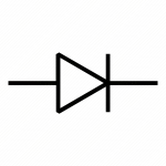
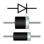
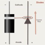
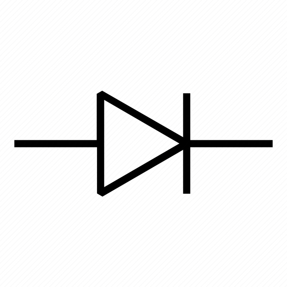
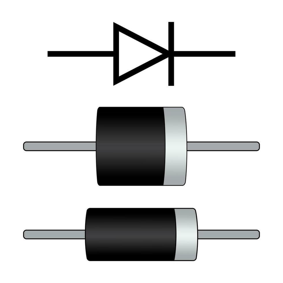
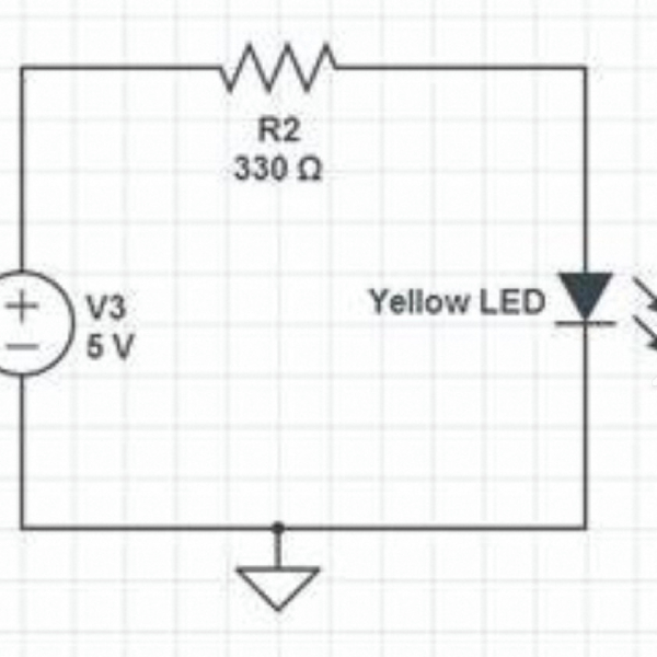
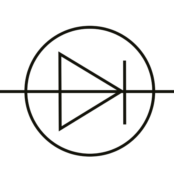
When you look at a diode symbol, you’ll see an arrow that points towards a line. This symbol is a map for how the current travels through the diode. It’s important to know which end is which. The arrow points from the anode to the cathode, indicating the direction of allowable current flow. The anode is the positive side, and the cathode is the negative side. Diodes also have physical markings – usually, a line on the component denotes the cathode side. Remembering this detail is vital for connecting diodes correctly in electronic circuits.
Diode Functionalities in Electronic Circuits
Blocking and Allowing Current Flow
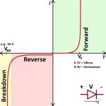
Diodes play a critical role in managing the direction of current flow in electronic circuits. When properly connected, a diode allows electricity to pass in only one direction. This is seen when the anode (positive side) is linked to the positive of a power source, and the cathode (negative side) to the negative. In this forward-bias setup, the diode works like a gate that lets current through. However, if the diode is reversed (reverse-bias), it blocks the current, acting like a dam and preventing any electrical flow. A semiconductor diode effectively regulates current flow, permitting passage in one direction while blocking it in the reverse, ensuring efficient circuit operation.
Sound Effects, AC to DC Conversion, and Voltage Spike Protection
Beyond basic current control, diodes serve in crafting sound effects. For instance, clipping in audio circuits is achieved with diodes, resulting in a distinctive overdrive used in guitar pedals. In power supplies, diodes are pivotal for converting AC (alternating current) to DC (direct current). By arranging four diodes in a bridge rectifier, they smoothly convert the current post-transformation. They also protect against damaging voltage spikes. Inductive components, like motors, generate these spikes. Diodes discharge them safely, shielding other circuit parts from harm. Diode laser wavelength technology complements the functions of diodes in sound and power applications by facilitating precise control and efficiency in various electronic circuits.
The Science Behind How Diodes Work
Diodes are fascinating devices, fundamental to countless electronic circuits. At their core lies a simple principle that dictates their function: current direction control. To understand this principle, we delve into the science of diodes. A diode schematic visually represents how these devices control current flow, demonstrating their essential role in electronic circuits.
The Role of the PN Junction and Depletion Region
A diode consists of two types of semiconductor material: the P-type and the N-type. The point where these materials meet forms the PN junction. In essence, the PN junction is the critical zone that gives the diode its unique properties.
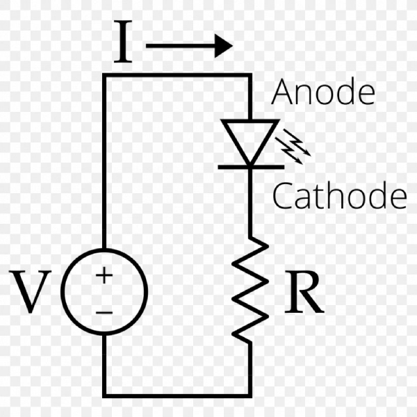
Now, imagine a barrier at this junction. We call this the depletion region. It’s like a no-man’s land that initially prevents any current from passing through the diode. Under normal conditions, this region acts as an insulator.
When we apply a positive voltage to the diode’s anode, the P-type side, something remarkable happens. The depletion region starts to shrink. This change allows current to flow from the anode to the cathode, which is how a diode conducts in its forward-biased state.
Switch the voltage around, and the depletion region grows, blocking any current from passing. This reverse-biased state turns the diode into a sturdy barrier against unwanted electrical current.
This duality is what makes diodes invaluable in circuits, be it for directing current, converting AC to DC, or protecting against voltage spikes. With this understanding of the PN junction and depletion region, we’ve peeked into the science that makes diodes work. A clear diode schematic illustrates the essential components of a diode, showcasing its role in directing current and preventing voltage spikes in electronic circuits.
Testing and Measuring Diode Characteristics
When working with diodes, it’s essential to understand their electrical characteristics. By testing these, we can ensure they fit the needs of our circuits. One crucial characteristic is the diode’s ability to conduct electricity in the correct direction.
Using a Multimeter to Determine Forward Voltage
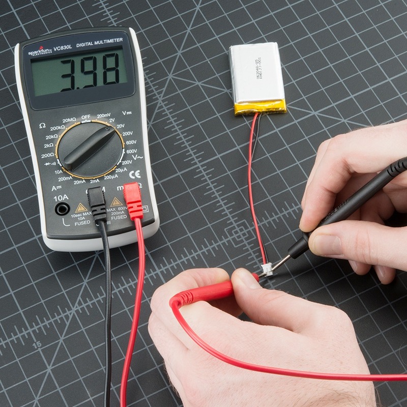
A multimeter is a handy tool for measuring a diode’s forward voltage. This is the voltage needed for the diode to conduct current. To test it, set your multimeter to the diode function, marked by a diode symbol. Connect the multimeter’s positive lead to the anode and the negative lead to the cathode.
The display will show the forward voltage when current begins to flow. This value is typically between 0.7 V and 1 V for silicon diodes. If the diode is functioning correctly, this voltage should be consistent with the diode’s specifications. Remember, testing the diode in reverse should not show any significant voltage, as current flow is blocked.
It’s important to note that a small leakage current might still pass when a diode is reverse-biased. However, if a high enough voltage is applied in the reverse direction, the diode can break down and allow current to flow. Ensure not to exceed the diode’s maximum reverse voltage during testing to prevent damage. When using a diode mode multimeter, be cautious of the small leakage current and avoid exceeding the diode’s maximum reverse voltage to ensure proper functioning.
Understanding Diode Biasing
Diode biasing is key to their function in circuits. Discussed simply, it’s how diodes know when to allow or block current. Let’s look closer at how this works.
The Impact of Forward and Reverse Biasing on Diode Performance
Forward biasing occurs when the anode connects to the positive, and the cathode to the negative. Here, diodes conduct electricity, helping currents flow correctl
y. In reverse bias, connections are swapped; positive to cathode, negative to anode. No current flows in this case. Diodes act like insulators, stopping any flow. Diode schematic symbols guide us in applying the proper bias.
Forward biasing is like opening a gate for electricity to pass through. Reverse biasing is like a barrier, keeping unwanted current out. Each biasing state has a huge impact on a circuit’s functioning. Diodes regulate current, converting AC to DC and pointed out by diode schematic, or prevent damage by blocking spikes.
Knowing how and when to bias diodes is crucial for circuit design. It ensures we use diodes to their full potential. Whether we’re lighting up LEDs or protecting against surges, diode biasing directs the play. A well-designed diode schematic maximizes the efficiency of circuit applications, whether for illuminating LEDs or surge protection.
Types of Diodes and Their Applications
Common Diodes: Signal, Rectifier, Zener, Schottky, and LEDs
Diodes come in many varieties, each with a specific purpose. Signal diodes, like the name suggests, handle small currents typical in signal processing applications. They’re essentially the same as rectifier diodes, but those are designed for higher power and current. Zener diodes are interesting because they can regulate voltage, acting as a precise voltage reference in circuits. Schottky diodes stand out for their low forward voltage drop and quick recovery time, making them ideal for fast-switching applications. LEDs, or light-emitting diodes, are a type of diode that emits light when current passes through them, widely used for indicators and illumination.
Specialty Diodes: Photodiodes and PIN Diodes
Photodiodes are sensitive to light and convert it into an electrical current, which is crucial for cameras and light detection circuits. PIN diodes have a layer of intrinsic semiconductor between the P and N layers, which allows them to work well at high radio frequencies, vital for radio and microwave applications. By understanding the different types of diodes and their uses, we can choose the right diode for the job. Whether it is managing power, detecting light, or emitting light, diodes play an essential role in a vast range of electronic devices. A comprehensive diode schematic can help visualize the diverse types of diodes and their specific applications in electronic devices.
Diode Specifications and Limitations
Every diode has its own set of specs that guide its use in circuits.
Forward Voltage Drop, PIV, and Maximum Current Ratings
Understanding diode specs is crucial for proper circuit design.
The forward voltage drop is key for a diode to start conducting. It’s the minimum voltage needed for current to flow. For many diodes, this voltage is about 0.7 V to 1 V. The forward voltage drop is a loss that a circuit must account for.
PIV stands for peak inverse voltage. It’s the max reverse voltage a diode can handle without damage. Exceeding this limit can cause the diode to fail, allow reverse current, and harm the circuit. Understanding the PIV is crucial in diode schematics to ensure safe voltage levels and prevent circuit damage from reverse current.
Diodes also have a max current rating. This is the most current they can handle safely. Going over this rating can overheat and destroy the diode. We must choose a diode that can safely manage the circuit’s power demands.
By respecting these specs, we can ensure that diodes work safely and effectively. Remember to consider the forward voltage drop, PIV, and max current rating when designing and testing circuits.
Implementing Diodes in Circuit Design
When crafting electronic circuits, integrating diodes properly is vital for success. There is much to consider in ensuring diodes function as intended within a circuit.
Practical Considerations for Diode Integration
Here are key points to keep in mind when using diodes in circuit design:
- Review Diode Specifications: Ensure the diode’s forward voltage drop, PIV, and maximum current ratings align with your circuit’s requirements.
- Correct Orientation: Always connect the anode to the positive and the cathode to the negative. A backward diode won’t function correctly.
- Heat Management: Diodes can generate heat when conducting. Plan for proper dissipation to prevent overheating and damage.
- Protective Measures: Use diodes to protect against voltage spikes, especially in circuits with inductive components like motors.
- Testing Before Use: Use a multimeter to test the diode’s forward voltage and ensure it matches the specification. This confirms its health.
- Choosing the Right Type: Match the diode type to its use: rectifier for power conversion, Zener for voltage regulation, LEDs for light, and so on.
- Beware of Reverse Voltage: Avoid exceeding the PIV rating. High reverse voltage can destroy the diode and the circuit.
- Current Limitations: Select a diode that can handle the expected currents without reaching its maximum current rating.
- Circuit Board Layout: Place diodes strategically to ensure they fit well and contribute to the circuit’s overall stability and performance. Keep track of the diode schematic symbols to avoid confusion.
- Environmental Conditions: Consider the operating environment. Extreme temperatures or humidity can affect diode performance.
By taking these practical steps, you’ll make the most of diodes in your designs, leading to robust and reliable electronic circuits.

