Introduction to Diode Mode
Diode mode on a multimeter is a handy feature designed especially for testing diodes. It allows technicians and hobbyists to measure the voltage drop across a diode when it is forward-biased. This mode is crucial because it can quickly indicate whether a diode is functioning correctly without removing it from a circuit.

When using diode mode, a small voltage is supplied by the multimeter to the diode. This helps in checking if the diode is passing current in the proper direction, which is the fundamental behavior of a diode. As such, diode mode becomes a diagnostic tool that provides insight into the health of a diode.
To begin testing, one must understand how to set up the multimeter and perform the test correctly. It is also essential to be able to interpret the readings that the multimeter displays in diode mode. This could range from a typical voltage drop, which is a good sign, to readings that suggest the diode is damaged. Understanding how to test a semiconductor diode correctly is crucial for ensuring its proper functionality and identifying potential issues.
Overall, diode mode is not just for diodes alone. It can also be useful for evaluating other semiconductor devices such as light-emitting diodes (LEDs), transistors, and Zener diodes. However, a clear grasp of the principles and procedures is necessary to ensure precision in testing and interpreting results.
Principles of Diode Testing
Understanding the principles of diode testing is pivotal for accurate diagnostics and troubleshooting in electronic circuits. Diode mode on a multimeter is made for this purpose. It tests diodes to ensure they allow current to flow in just one direction. This is in line with the basic functionality of a diode, which is to permit current flow when forward-biased and block it when reverse-biased. A diode schematic is essential for comprehending how diodes operate in circuits, illustrating their role in controlling current flow direction as tested by a multimeter.
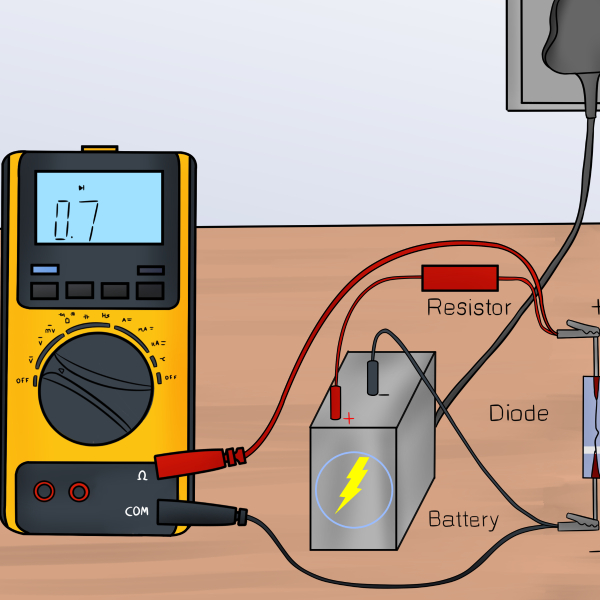
Proper testing involves a step-by-step approach: identify the diode’s anode and cathode terminals, set the multimeter to diode mode, connect the multimeter probes to the diode, and observe the readings. A healthy diode typically shows a forward voltage drop between 0.5 and 0.8 volts for silicon diodes when forward-biased. It shows ‘OL’ (overload) when reverse-biased, indicating that it’s blocking current as expected. Deviations from these readings may suggest a problem.
It’s important to remember that these procedures might need adjustment if the diode is part of a complex circuit. Factors such as residual currents from other components can affect readings. For the exact procedures, ensure that the circuit power is off and the diode is isolated if necessary. This ensures that true diode behavior is captured.
By adhering to these principles, you can employ the diode mode on your multimeter effectively. This helps in detecting faulty diodes and ensures the reliability of electronic devices and circuits.
How to Use Diode Mode on a Multimeter
To effectively use diode mode, accurately setting up your multimeter is key. Here’s a clear, step-by-step guide to help you through the process.

Preparing for the Test
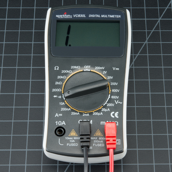
Begin by ensuring the diode and the circuit it belongs to is without power. This prevents incorrect readings due to current from other components. Next, set the multimeter to diode mode, visually confirmed by the diode symbol on the multimeter. Once in diode mode, confirm that your probes are in the appropriate ports – typically, the black probe in the common port and the red probe in the port marked for voltage and resistance. Handle the probes with care to avoid any accidental short circuits.
Forward Bias Testing
Identify the diode’s anode and cathode – the anode is the positive end, while the cathode is marked with a band and is negative. Connect the red probe to the diode’s anode and the black probe to the cathode. This sets up the diode in forward bias, allowing current to flow. The multimeter will read the voltage drop across the diode – for silicon diodes, this should be between 0.5V and 0.8V. If the reading falls within this range, your diode is typically functioning as it should. The diode laser wavelength can be effectively assessed by ensuring the diode is functional, following the proper anode and cathode connections during testing.
Reverse Bias Testing
For reverse bias testing, simply swap the connections – red probe to the cathode and black to the anode. A healthy diode should show ‘OL’ on the multimeter, indicating no current flow in reverse bias. If there’s any reading other than ‘OL’, this could signify a problem with the diode, such as being shorted.
By following these steps, you can safely and clearly test diodes using your multimeter’s diode mode. This allows you to quickly identify if the component is working correctly or if it requires replacement. It’s important to always observe safety and take the necessary precautions when working with electrical devices and tools.
Interpreting Diode Mode Readings
Understanding what your multimeter displays in diode mode is crucial for diagnosing diode health. The readings provide valuable insights into a diode’s status, offering either a confirmation of functioning or a signal that something is wrong. Here is a simple explanation of the key readings you might encounter.
Normal Diode Voltage Drop
In diode mode, a healthy silicon diode typically shows a voltage drop when it is forward-biased. For silicon diodes, expect to see a readout between 0.5V and 0.8V. This indicates that the diode is conducting current as it should. If you’re testing a germanium diode, the normal voltage drop will be around 0.2V to 0.3V. These numbers reflect a normal function and suggest the diode is working correctly.
Identifying Damaged Diodes
A damaged diode will not show the standard voltage drops mentioned. If your multimeter reads ‘OL’ or a very high voltage in forward bias, the diode may be open and not conducting. Conversely, if it shows any voltage significantly lower than the expected range, or if it reads a value when reverse-biased (other than ‘OL’), the diode might be shorted. Both cases indicate a diode that is not operating properly and likely needs replacement. By understanding these readings, you can quickly decide if a diode is healthy or requires attention. This helps maintain the reliability of your electronics projects or repairs.
Advantages of Diode Mode in Circuit Analysis
Diode mode on a multimeter greatly aids circuit analysis in several ways. Firstly, it simplifies the testing process by allowing quick identification of diode functionality without desoldering or isolating the component. This saves time, especially when handling complex boards with multiple diodes.
Secondly, diode mode provides a precise measurement of the voltage drop across the diode when forward-biased. This precision is critical in diagnosing potential issues with the diode. It can reveal whether the diode is conducting correctly or if there’s a fault that needs further investigation.
Thirdly, diode mode contributes to safety by ensuring tests are carried out without power in the circuit. It prevents the risk of short circuits or damage to the multimeter and other components. By using diode mode, you can avoid creating new issues while trying to solve existing ones.
Lastly, diode mode can quickly indicate a diode’s polarity which is essential when checking the orientation in a circuit. Correct polarity is fundamental for the diode to function properly and for the overall circuit to operate as intended.
In summary, diode mode is a practical tool for circuit analysis that simplifies testing, enhances precision, promotes safety, and confirms component orientation. It should be a key part of any electronics diagnostic toolkit.

Testing Other Semiconductor Devices with Diode Mode
Diode mode on a multimeter is not limited to testing just standard diodes. It’s also an effective way to evaluate the condition of other semiconductor devices such as LEDs, transistors, and Zener diodes. These components have their unique characteristics which can be analyzed using the diode test function. However, it is crucial to know their testing differences to avoid damage or incorrect readings.
Testing LEDs
LEDs, or Light Emitting Diodes, can be tested using diode mode. To test an LED, you connect the positive (red) probe to the longer lead, the anode, and the negative (black) probe to the shorter lead, the cathode. A properly working LED will light up slightly and show a forward voltage drop. This drop is typically higher compared to regular diodes, often between 1.7V and 3V, depending on the LED color.
Examining Transistors
Transistors can also be assessed using diode mode. A transistor has three terminals: base, collector, and emitter. By treating the base-emitter and base-collector junctions as diodes, you can verify if these paths are working. Each junction should show a forward voltage drop similar to a standard diode when forward-biased. If the multimeter shows ‘OL’ in the forward direction, the junction may be open.
Checking Zener Diodes
Zener diode testing is a bit more complex because they operate differently than regular diodes. They are designed to conduct in reverse bias at a specific voltage known as the Zener voltage. To test them, a series resistor is used to limit current, and then the Zener diode is reverse-biased. The multimeter should show a voltage reading close to the diode’s Zener voltage if it’s working correctly.
Understanding how to use diode mode to test different types of semiconductor devices extends the functionality of your multimeter and enhances your troubleshooting abilities.
Common Misconceptions and Mistakes
When using diode mode on a multimeter, common mistakes can lead to incorrect diagnoses. Understanding these can improve testing accuracy.
Misunderstanding Voltage Readings
A frequent error is misinterpreting voltage drops. Not all voltage drops below 0.8V indicate a healthy silicon diode. Temperature variations and particular diode types can alter this range. For accurate results, consider these factors when evaluating readings.
Incorrect Test Lead Placement
Another mistake is placing test leads incorrectly. This can happen if one does not remember the diode’s polarity. Always connect the red lead to the anode and the black lead to the cathode in forward bias testing. Reverse the leads for checking reverse-current blocking.
Testing Diodes in Circuit
Testing diodes without removing them from circuits can also mislead. Other components in the circuit can influence the multimeter’s reading. Best practice is to isolate the diode, or account for potential discrepancies if in-circuit testing.
Overlooking Faulty Equipment
Sometimes, the issue may be the multimeter itself. Using a faulty or uncalibrated multimeter could provide false readings. Regular maintenance and calibration are crucial for trustworthy measurements.
Applying Excessive Current
Applying too much current can damage diodes during the test. The multimeter’s internal battery typically supplies a safe current level in diode mode. Ensure the multimeter is in the correct mode to prevent damage.
By avoiding these common mistakes, you can ensure more reliable and accurate diode tests. Take the time to follow proper testing procedures and understand the multimeter’s readings for best results.
Conclusion: Ensuring Accurate Diode Tests
Ensuring accurate diode tests is crucial for the effective use of electronic devices. Diode mode multimeter testing allows precise checks on diode functionality. To achieve reliable results, follow these final guidelines:
- Always begin with safety. Ensure the circuit is powered down before testing.
- Identify diode terminals. Know your anode from your cathode to avoid confusion.
- Use diode mode correctly. Set your multimeter properly and use the right testing method.
- Interpret readings carefully. Recognize what the different measurements indicate about your diode’s health.
- Remember, various semiconductor devices require different testing approaches. Apply the right technique for LEDs, transistors, and Zener diodes.
- Check your tools. Verify your multimeter’s accuracy to avoid skewed results.
- Avoid common mistakes, such as wrong lead placements or remaining in a live circuit.
By adhering to these practices, you can confidently assess the condition of diodes and other semiconductors. Accurate testing is essential for diagnosing issues, preventing equipment failure, and ensuring the longevity of electronic circuits. Always aim to refine your understanding of diode testing for excellence in electronics troubleshooting and repair.


