Introduction to Diode Resistance
Understanding diode resistance is crucial for electronic circuit design and troubleshooting. A diode’s resistance determines how it will behave in a circuit, particularly whether it will let current flow or block it. Simply put, diode resistance is the opposition a diode offers to current flow. It varies depending on whether the diode is forward-biased or reverse-biased.
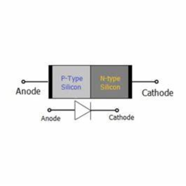
Diodes are semi-conductor devices that direct current in one direction. They have two states: forward-biased when they conduct electricity, and reverse-biased when they block it. However, even in the forward state, a diode does not conduct perfectly – it has resistance. This resistance is important to consider in circuit design to ensure components operate safely and efficiently.
In the reverse state, ideally, a diode’s resistance would be infinite, completely blocking current. In reality, this is not the case due to leakage currents, making the understanding of diode resistance a nuanced matter.
In the following sections, we will delve into various aspects of diode resistance, including its behavior under different biases, how to measure it, and typical values you might encounter in circuits. This knowledge is essential for anyone working with or interested in electronics, whether you are a student, hobbyist, or professional engineer.
Basic Concepts of a Diode
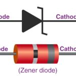
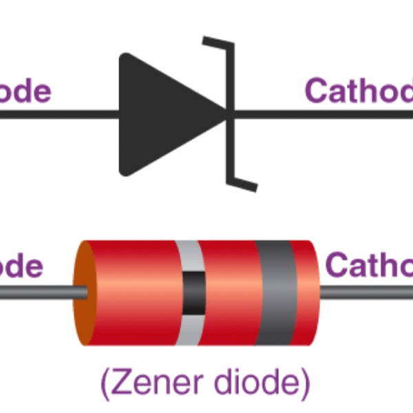
Before diving into the specifics of diode resistance, let’s clarify the basic concepts of a diode. A diode is a semiconductor device that allows current to flow primarily in one direction. It has two terminals: an anode (+) and a cathode (-). The direction in which a diode conducts current is important for understanding its resistance characteristics. When considering a microwave diode replacement, it’s essential to understand the fundamental operation of diodes, as their directional current flow significantly influences their resistance characteristics and overall performance in circuit applications.
Diodes are fundamental components in electronic circuits. They serve various purposes, such as rectifying alternating current (AC) to direct current (DC), isolating signals, and protecting circuits from voltage spikes. To fully grasp diode resistance, you need to understand how diodes function in these roles.
Key attributes of diodes include:
- Unidirectional current flow: A diode conducts current easily from anode to cathode under certain conditions.
- Threshold voltage: Diodes have a voltage threshold that must be met before they can conduct.
- Depletion region: This is the area at the p-n junction that affects the diode’s resistance properties.
In summary, a diode’s ability to control the flow of current makes it indispensable in electronics. Its behavior under different conditions leads to various resistance levels, which we will explore in the subsequent sections.
Forward-Biased vs. Reverse-Biased Diode Behavior
When we talk about diodes, we often mention two states: forward-biased and reverse-biased. These states determine how the diode reacts to current. Understanding these behaviors is key for anyone working with electronics.
Forward-Biased Diode Behavior
In a forward-biased state, the diode allows current to flow. This happens when the positive voltage is applied to the anode and negative to the cathode. The diode’s internal resistance drops, and current passes through easier. However, even in this state, a diode has what we call ‘forward resistance.’ It’s not zero but low enough to let a significant current pass. Understanding the diode dynamics ss3 pro helps clarify how a diode operates in a forward-biased state, where it permits current flow while maintaining a low forward resistance, ensuring efficient conduction without reaching a zero-resistance scenario.
When a diode is forward-biased, the voltage across it needs to surpass a certain threshold. For silicon diodes, this is typically around 0.6 to 0.7 volts. Once this threshold is crossed, the diode conducts, and the current flows. The flow of current is due to the reduction of the depletion region at the p-n junction.
Reverse-Biased Diode Behavior
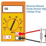
Contrastingly, in a reverse-biased state, the diode blocks current flow. The positive voltage is applied to the cathode and negative to the anode. This expands the depletion region, increasing the diode’s resistance drastically. In an ideal scenario, a reverse-biased diode would have infinite resistance, absolutely blocking current.
However, in reality, a small leakage current can still flow. This is due to minority charge carriers. The resistance in reverse bias is very high, though, often reaching megaohms. Thus, for practical purposes, the diode in reverse bias effectively acts as an open circuit, barring any significant current flow.
When using a diode tester, it’s important to remember that while a reverse-biased diode appears as an open circuit, a small leakage current may still be present due to minority charge carriers, even though the resistance is extremely high.
To sum up, diode behavior in circuits changes with its biasing. In a forward bias, diodes conduct with low resistance. In reverse bias, they block current with high resistance. These traits are fundamental to using diodes in circuit design and for managing current flow.
Static and Dynamic Resistance Explained
When discussing diode resistance, it’s essential to recognize two distinct types: static and dynamic resistance. Each has a role in how diodes behave in electrical circuits.
Static Resistance
Static resistance, or DC resistance, refers to the opposition a diode offers to direct current (DC) flow. This resistance is constant over a wide range of operating conditions. One key way to understand static resistance is through the diode’s V-I (voltage-current) characteristics. The formula for calculating static resistance is R_DC = V_D / I_D, where V_D is the voltage across the diode and I_D is the current flowing through it. Typically, static resistance is low for a forward-biased diode and extremely high for a reverse-biased diode.
Dynamic Resistance
In contrast, dynamic resistance, or AC resistance, is the opposition a diode offers to alternating current (AC). Unlike static resistance, dynamic resistance changes with the AC signal’s frequency. It’s calculated as the ratio of a small change in voltage to a small change in current (r_ac = ΔV / ΔI). Dynamic resistance is vital when diodes are used in circuits with varying signal levels, such as in radio frequency or digital applications.
Understanding static and dynamic resistance helps in designing circuits that leverage diodes effectively. Whether you’re using diodes for rectification, signal processing, or voltage regulation, recognizing the type of resistance at play is crucial for achieving the desired circuit behavior. By measuring and comparing these resistances, engineers can determine diode suitability for specific applications and ensure electronic devices function reliably.
Measuring Diode Resistance using Multimeters
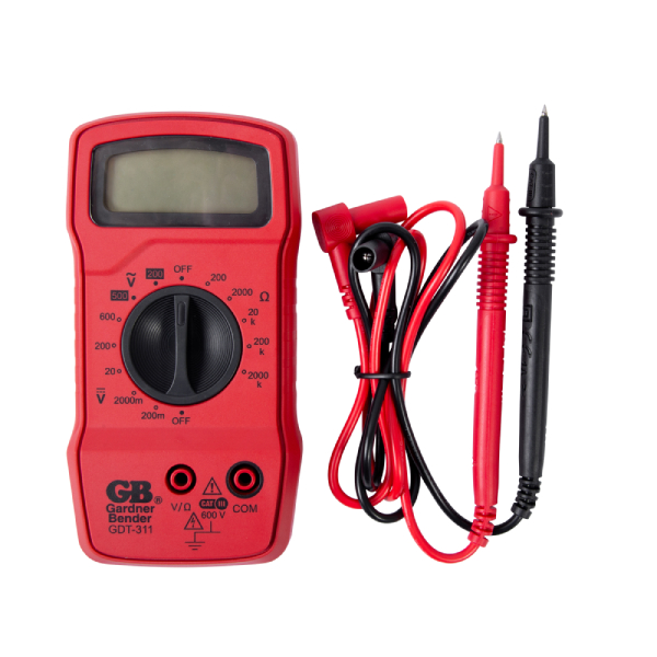
Measuring diode resistance accurately involves using a multimeter. A precise understanding of the process aids in effective diagnostics and circuit analysis. Multimeters come built with capabilities that can check the resistance of diodes. Here’s a simple guide to perform this essential test.
Steps to Measure Diode Resistance
- First, ensure that all power is off and voltage is not present in the circuit. This is crucial for safety and to prevent multimeter damage.
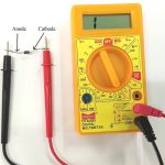
- Set your multimeter to the Diode Test mode if available. This produces a small voltage to measure forward bias drop.
- If the Diode Test mode isn’t available, set the multimeter to Resistance mode.
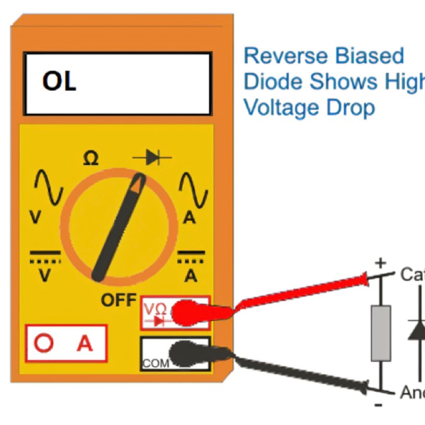
- Connect the multimeter’s red test lead to the diode’s anode and the black to the cathode.
- Note the reading, which should be between 0.5 to 0.8 volts for a good silicon diode.
- For the reverse bias test, swap the test leads. The multimeter should show an ‘OL’ or high resistance.
- If the diode shows low resistance in both directions, it might be shorted. If ‘OL’ appears in both directions, the diode could be open.
Interpreting the Results
A forward-biased diode shows low resistance because it’s conducting current. In reverse bias, high resistance indicates the diode is blocking the flow. Anomalies in these readings suggest potential issues with the diode. Regular tests with a multimeter help maintain circuit integrity and prevent failures.
Common Diode Resistance Values and Ranges
When working with diodes in electronic circuits, knowing the typical resistance values is important. These values give us a baseline for what to expect during testing and troubleshooting. Here’s an overview of common diode resistance values and ranges that you might encounter.
Forward-Biased Diode Resistance
In a forward-biased state, silicon diodes usually show a voltage drop between 0.5 and 0.8 volts. This correlates with a resistance typically lower than 1 ohm. However, germanium diodes tend to have lower voltage drops, around 0.2 to 0.3 volts. The actual resistance will vary based on the diode’s material and manufacturing quality.
Reverse-Biased Diode Resistance
When reverse-biased, diodes display high resistance, often in the megaohms range. This is because the expanded depletion region at the p-n junction creates a significant barrier for current flow. For practical purposes, we consider this as near infinite resistance, though leakage currents are still possible.
By understanding these typical values, we can better assess the performance of diodes in circuits. We ensure our expectations are in line with standard behaviors. We also recognize when a diode may not be functioning correctly. As we apply this knowledge, we maintain the health and efficiency of our electronic designs.
Analysis of Diode Resistance in Circuit Design
In circuit design, understanding diode resistance is key to ensuring device safety and efficiency. When designers analyze circuits, they consider the diode’s forward and reverse resistance. This helps them predict how the diode will behave under different electrical stresses. It’s crucial to select the right diode with appropriate resistance levels for the intended application.
Designers must account for the diode’s threshold voltage and expected current flow. In forward bias, the diode’s low resistance allows for current flow, once the threshold voltage is surpassed. However, this forward resistance must be factored into the total circuit resistance to prevent overloading other components.
For reverse bias, the high resistance of the diode is beneficial. It protects circuits from unwanted current reversal, which can damage sensitive electronics. This high resistance also helps in managing power dissipation across the diode, ensuring it does not overheat or fail.
In sum, diode resistance affects the overall impedance, stability, and performance of electronic circuits. Designers use it to guide the placement and function of diodes within circuit layouts. By analyzing these resistance values, they can optimize circuit designs for reliability and functionality.
Troubleshooting Diode Resistance Issues in Electronics
Troubleshooting diode in electronics is a crucial skill for ensuring circuits function correctly. Diode issues can arise from several factors including manufacturing defects, wear and tear, and improper usage. Diagnosing these issues typically involves three main steps: visual inspection, testing with a multimeter, and comparing findings with expected behavior.
Visual Inspection of Diodes
Start with a close visual check of the diode. Look for obvious signs of damage, such as cracks, burn marks, or discoloration. If the diode’s physical state is compromised, it may not function properly, affecting resistance.
Testing Diodes with a Multimeter
Multimeter tests provide more insight into diode health. To check diode resistance:
- Power off the circuit and ensure no voltage is present.
- Set the multimeter to diode test mode, if available.
- Apply multimeter leads to diode terminals, noting the forward-biased reading.
- Swap leads and record the reverse-biased reading.
- Diodes showing abnormal resistance in either direction need further evaluation.
Comparing Expectations with Reality
When testing diode resistance, compare your multimeter readings with expected values. A good silicon diode typically shows 0.5 to 0.8 volts in the forward direction. A reverse-biased diode should show ‘OL’ or high resistance. Readings outside these ranges suggest potential issues.
Troubleshooting is about combining knowledge of diode resistance with practical testing. By identifying and addressing resistance problems, you maintain circuit integrity and prevent potential failures. Remember to follow safety protocols and disconnect power before any testing to avoid damage and ensure accuracy.
