Diodes are essential components in any electronic circuit. They allow current to flow in one direction while blocking it in the opposite direction. This property makes them useful in various applications, from rectification to signal processing. Testing a diode ensures it operates correctly in your circuits. In this guide, we will cover the importance of testing diodes, methods to test them, and some troubleshooting tips.
 1. Understanding Diodes
1.1 What is a Diode?
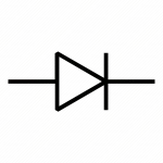
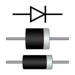
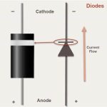
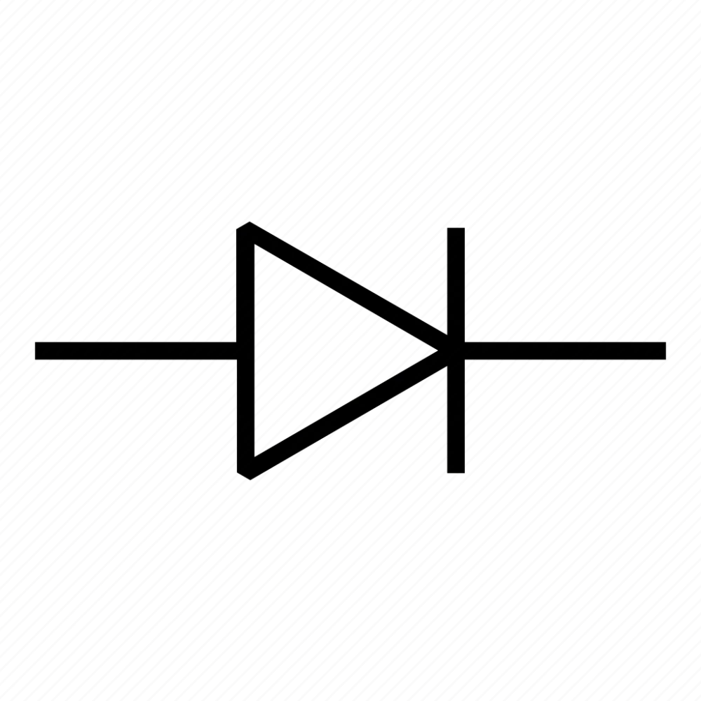
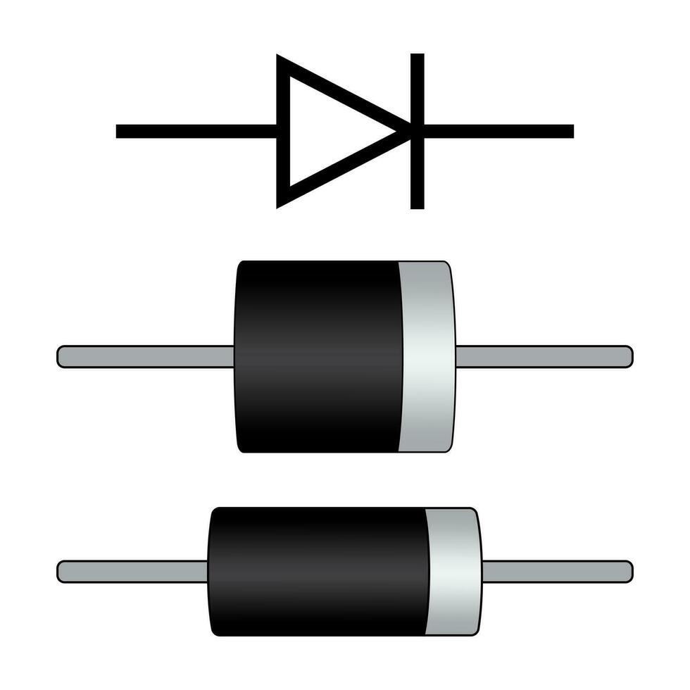
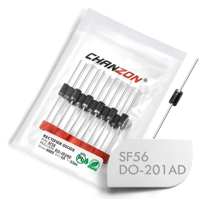
A diode is a semiconductor device that has two terminals, known as the anode and cathode. The basic function of a diode is to allow current to flow in one direction. For example, when voltage is applied to the anode, the diode conducts electricity. However, if the voltage is reversed, current does not flow.
1.2 Types of Diodes
There are many types of diodes. Some common ones include:
- Rectifier Diodes: Used in power supply circuits.
- Zener Diodes: Used for voltage regulation.
- Light Emitting Diodes (LEDs): Emit light when current flows through them.
- Schottky Diodes: Known for their fast switching speeds.
Each type of diode has a unique purpose and characteristics. However, the basic testing methods remain consistent across all types.
2. Why Test a Diode?
2.1 Ensuring Proper Functionality
Testing a diode ensures that it is functioning correctly. A broken diode can lead to circuit failure. If a diode does not conduct in the forward direction, it can stop current flow where it is needed. Conversely, if it conducts in the reverse direction, it can cause damage to other components.
2.2 Preventing Circuit Damage
Using a faulty diode can lead to damage in the circuit. If a diode fails open (doesn’t conduct in forward direction), it may seem like a simple issue. However, in some cases, it can lead to higher voltages than expected. This can damage other parts connected to the circuit.
2.3 Saving Time and Money
By testing diodes regularly, you can catch problems early. This practice minimizes troubleshooting time and prevents costly repairs. Knowing the status of a diode helps in planning maintenance and replacement schedules.
 3. Tools Required for Diode Testing
Before you begin testing a diode, gather the necessary tools.
3.1 Multimeter
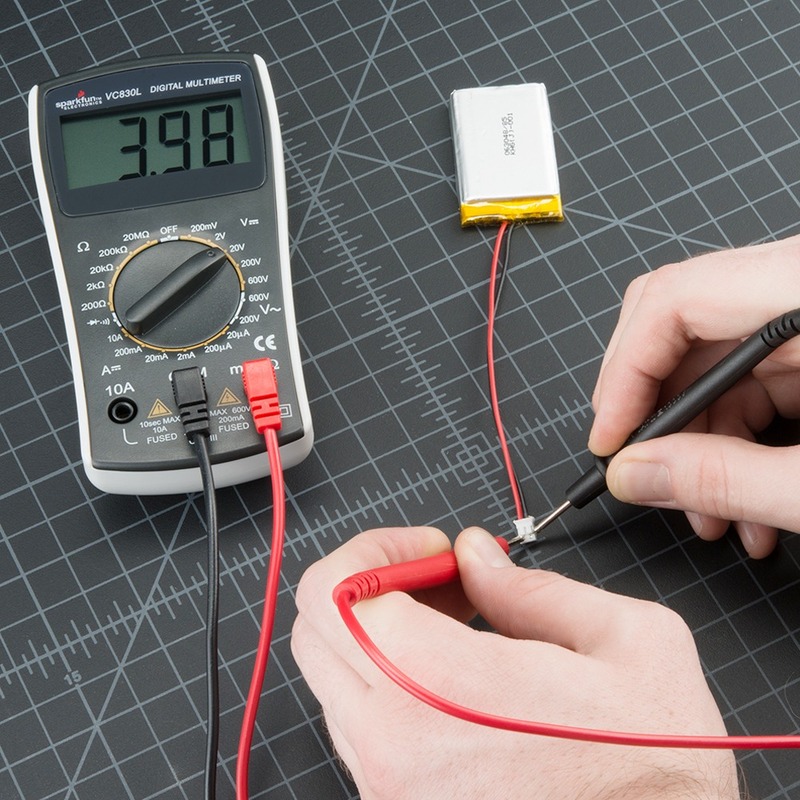
A digital multimeter (DMM) is the primary tool for testing diodes. The DMM will have a diode testing function. This feature allows you to measure the forward and reverse voltage drop across the diode.
3.2 Oscilloscope (Optional)
An oscilloscope may be useful for more advanced testing. With it, you can observe the diode’s response to changing signals. This is particularly helpful in identifying issues in signal applications.
3.3 Test Leads
Make sure you have quality test leads for your multimeter. They should be in good condition to ensure accurate measurements. Poor leads can give misleading readings.
4. Methods for Testing Diodes
There are multiple methods for testing diodes. Below we outline the most common and effective techniques.
4.1 Using a Multimeter
4.1.1 Setting Up the Multimeter
- Turn on your multimeter.
- Set it to the diode testing mode. This setting is usually indicated by a diode symbol.
4.1.2 Testing the Diode
- Forward Bias Test:
- Connect the positive lead to the anode.
- Connect the negative lead to the cathode.
- The multimeter should display a reading (typically between 0.2V to 0.7V for silicon diodes).
- Reverse Bias Test:
- Switch the leads: connect the positive lead to the cathode and the negative to the anode.
- The multimeter should display “OL” (overload) or infinity. This indicates the diode is blocking current.
4.1.3 Interpreting the Results
- Good Diode: Forward voltage drop is within the expected range, and it blocks reverse current.
- Bad Diode: Forward voltage is very high or zero, or it conducts in reverse.
 4.2 Testing with a Power Supply
This method is useful for testing diodes in working circuits.
4.2.1 Equipment Needed
- A bench power supply.
- Load resistor (to limit current).
- Multimeter to measure voltage.
4.2.2 Procedure
- Connect the diode in series with the load resistor and power supply.
- Set the power supply to a low voltage.
- Measure the voltage across the diode.
4.2.3 Analyzing the Results
- A functional diode will show a specific forward voltage drop.
- If the voltage appears significantly higher or lower, the diode may be faulty.
 4.3 Using an Oscilloscope
This method allows you to observe the diode characteristics visually.
4.3.1 Setting Up the Oscilloscope
- Connect the probe to the diode.
- Set the oscilloscope to the appropriate time/div settings for your signal.
4.3.2 Observing the Signal
- Apply a signal across the diode.
- Look for the expected forward and reverse characteristics.
4.3.3 Diagnosing Issues
- A healthy diode will show expected waveform shapes.
- Any distortions or unexpected voltages may indicate a problem.
5. Common Problems in Diode Testing
When testing diodes, you may encounter some common issues.
5.1 Open Diode (Non-Conducting)
If a diode is tested and does not conduct at all, it may be open. An open diode will have infinite resistance in both directions. Replace an open diode to ensure circuit functionality.
5.2 Shorted Diode (Conducting Both Directions)
If a diode conducts in both forward and reverse, it is shorted. A shorted diode will read near-zero resistance in both directions. This can cause significant circuit issues. Replacing the shorted diode is necessary.
5.3 Reverse Leakage
Some diodes may show slight conduction in reverse. This is known as reverse leakage. For most applications, this should be minimal. If the leakage is high, it may indicate a failing diode and should be replaced.
6. Troubleshooting Diode Issues
If you suspect a diode is not working, follow these troubleshooting steps.
6.1 Check Connections
Make sure all connections are secure. A loose or corroded connection can yield misleading results.
6.2 Confirm Multimeter Settings
Ensure your multimeter is set to the diode test mode. Incorrect settings may lead to inaccurate readings.
6.3 Inspect the Diode Physically
Look for visual signs of damage, such as burns or cracks.
6.4 Confirm Circuit Design
Sometimes the issue lies not with the diode but with the circuit design. Ensure the circuit is designed correctly and that the diode is suited for its application.
 Some key trends:
The popularity of diodes has been influenced by various technological advancements and market demands. Here are some key trends:
Miniaturization: With the growing need for smaller electronic devices, manufacturers are producing more compact and efficient diodes, such as SMD (Surface Mount Devices) types.
High-Power Applications: As industries pursue renewable energy solutions, high-power diodes, such as silicon carbide (SiC) and gallium nitride (GaN) diodes, are gaining popularity for their efficiency in high-voltage and high-temperature environments.
Integration with Advanced Technologies: Diodes are increasingly integrated into complex systems like electric vehicles, smart grids, and IoT devices, driving demand for specialized diode types.
Increased Demand for Energy Efficiency: The push for greener technologies has led to a rise in the development of diodes that minimize energy loss, contributing to lower overall power consumption.
Emerging Markets: The growth of emerging markets in electronics, renewable energy, and automotive sectors has further amplified the need for various types of diodes.
Overall, the diode market is evolving rapidly, adapting to technological innovations and shifting consumer preferences, making them a vital component in modern electronics.
7. Conclusion
Testing a diode is a vital procedure in electronics. It ensures that circuits function as intended, prevents damage, and saves time and money in repairs. Using a multimeter is the most common method for testing diodes. However, for more complex diagnostics, an oscilloscope can provide valuable insights.
Next time you suspect a diode issue, remember the methods outlined in this guide. With the right tools and knowledge, you can easily ensure your diodes are working correctly. Happy testing!

