 Introduction
Diodes are essential electronic components used in various circuits to control the flow of current. Checking a diode is necessary to ensure that it is functioning correctly and to troubleshoot any issues in a circuit. In this article, we will provide a simple guide on how to check a diode effectively. By following these straightforward steps, you can easily determine the condition of a diode and ensure its proper functioning.
How to check a diode
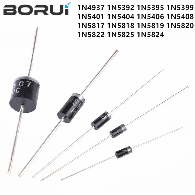
 Some common types of diodes:
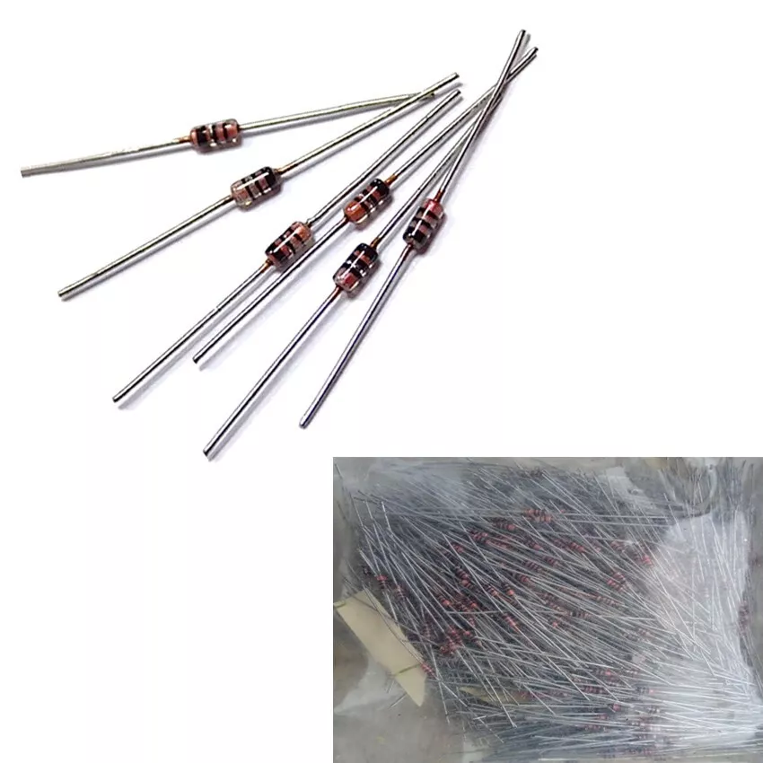
Diodes can be classified into different types based on their construction, material, and functionality. Here are some common types of diodes:
PN Junction Diode:
The PN junction diode is the most basic and common type of diode.
Schottky Diode:
Schottky diodes are constructed using a metal-semiconductor junction instead of a PN junction. They have fast switching speeds and a lower forward voltage drop, making them suitable for high-frequency applications and rectification tasks.
Light Emitting Diode (LED):
LEDs are special diodes that emit light when forward biased. They are widely used in various applications, including displays, indicators, lighting, and optoelectronics.
Photodiode:
Photodiodes are designed to convert light energy into electric current. They are used in light sensing and detection applications, such as optical communications, solar cells, and light meters.
Varactor Diode:
Their capacitance varies with the applied voltage, allowing them to function as voltage-controlled reactive elements.
Avalanche Diode:
Avalanche diodes are designed to operate in the reverse breakdown region. They are utilized for their ability to handle large reverse voltages and provide protection against voltage surges or transients.
These are just a few examples of the many diode types available. Each type has its own unique characteristics and applications, catering to different electronic circuit requirements.
 Some specific roles and uses of diodes:
A diode is an electronic component that primarily serves as a one-way valve for electrical current. Its main function is to allow current to flow in one direction while blocking current flow in the opposite direction. Here are some specific roles and uses of diodes:
Rectification:
One of the most common applications of diodes is in rectifiers. Diodes are used to convert alternating current (AC) to direct current (DC) by allowing current flow in only one direction. They block the negative half of the AC waveform, allowing only the positive half to pass through.
Current Protection:
Diodes can also be used for preventing damage to sensitive components or circuits from reverse current or voltage spikes. They act as a protective barrier by allowing current flow in the forward direction while blocking or limiting current flow in the reverse direction.
Voltage Regulation:
Diodes are often incorporated in voltage regulators and voltage reference circuits. They maintain a constant voltage output by regulating and stabilizing the voltage applied to a circuit or device.
Signal Demodulation:
Diodes are integral in demodulating signals, particularly in communication systems. They convert radio frequency (RF) signals or amplitude-modulated (AM) signals back into their original baseband signals by rectifying and filtering the incoming waveform.
Light Emitting Diodes (LEDs):
Light emitting diodes are a special type of diode that emits light when current passes through it. LEDs are widely used in applications such as displays, indicators, signage, and lighting.
These are just a few examples of the various roles and applications of diodes in electronic circuits and systems. Diodes play a critical role in controlling current flow, protecting components, and enabling various functions and operations in electronic devices.
Understanding Diodes
How to check a diode
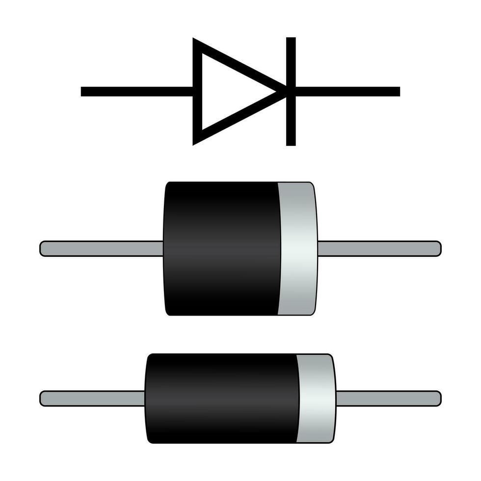
Definition: A diode is a two-terminal electronic component that allows current to flow in one direction while blocking it in the opposite direction.
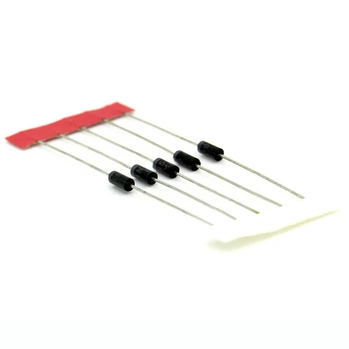
Types of Diodes: Various types of diodes exist, including the standard silicon diode, light-emitting diode (LED), Schottky diode, and Zener diode, each with its unique characteristics and applications.
Tools Required for Diode Testing
How to check a diode
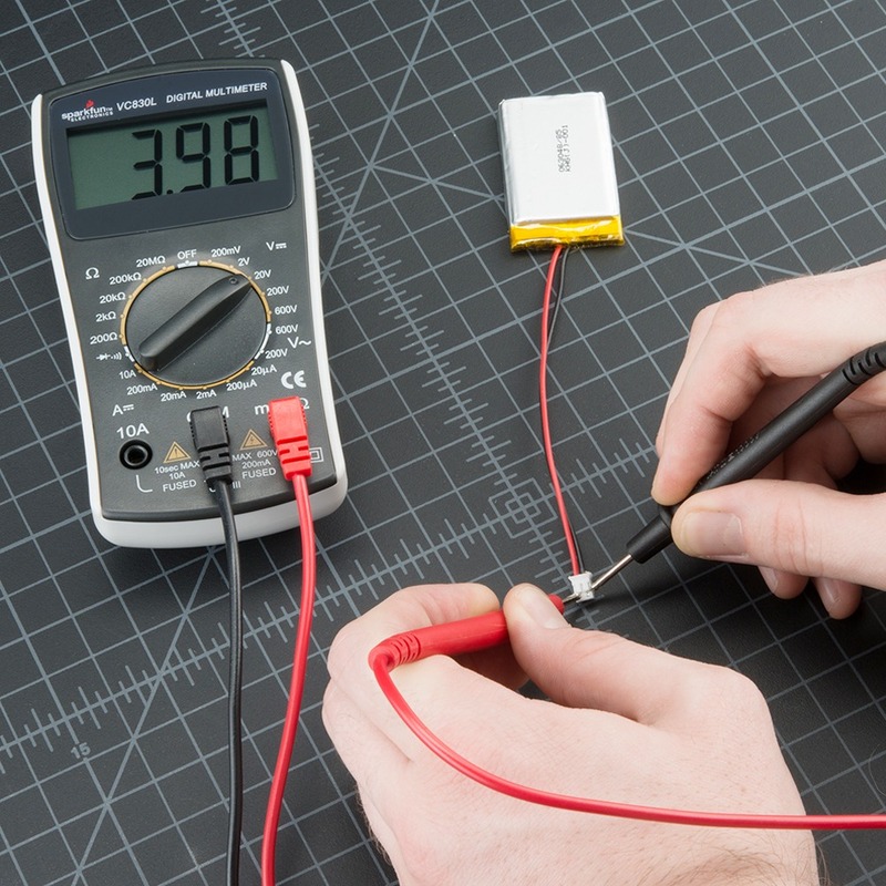
Multimeter: A digital multimeter capable of measuring resistance and voltages is essential for diode testing. Set the multimeter to the diode testing mode (usually indicated by a diode symbol or the letter “D”).
Test Leads: Ensure you have the necessary test leads or probes to make the required connections between the diode and the multimeter.
 Testing a Diode with a Digital Multimeter
Diode Orientation:
Identify the diode’s orientation, as it typically has a stripe or other marking indicating the cathode (negative) side. Make a note of this orientation.
Resistance Testing:
Begin by measuring the resistance of the diode. Connect the black test lead to the negative terminal of the diode and the red test lead to the positive terminal. Note the resistance reading on the multimeter display.
Forward Bias Test:
To test the diode’s forward bias condition (current flowing through it), connect the red test lead to the diode’s anode (positive) side and the black test lead to the cathode (negative) side. Note the voltage reading on the multimeter, which should be around 0.6 to 0.7 volts for a standard silicon diode.
Reverse Bias Test:
Test the diode’s reverse bias condition (blocking the current flow) by reversing the test lead connections, i.e., connecting the red test lead to the diode’s cathode side and the black test lead to the anode side. The multimeter should display an overload or infinite resistance, indicating that the diode is blocking the current.
Interpreting the Results
How to check a diode
Normal Diode: A normal diode will display low resistance in forward bias (conducting) and high resistance in reverse bias (blocking).
Shorted Diode: If the multimeter shows low resistance in both forward and reverse bias, it suggests a shorted diode, meaning it is conducting in both directions.
Open Diode: If the multimeter shows high resistance in both forward and reverse bias, it indicates an open diode, meaning it is not conducting in either direction.
Test a diode using a diode tester or multimeter
To test a diode using a diode tester or multimeter, you can follow these steps:
Set the multimeter to the diode testing mode. Look for the diode symbol (usually represented by an arrow pointing towards a vertical line) on the multimeter dial or digital display. It may also be labeled as “diode test” or “forward bias test.”
Identify the cathode and anode terminals of the diode. The cathode is typically identified by a stripe or line near one end of the diode or a flat side, while the anode is the other end. Make sure to connect the diode correctly during testing.
Connect the multimeter leads to the diode terminals. Connect the positive (red) lead to the anode of the diode and the negative (black) lead to the cathode.
Read the multimeter display. The multimeter will display a voltage drop across the diode when a positive voltage is applied to the anode and negative voltage to the cathode. A functional diode will typically show a voltage drop of around 0.6 to 0.7 volts (for silicon diodes) or 0.2 to 0.3 volts (for germanium diodes).
Reverse the leads and retest. Disconnect the leads and reconnect them, this time with the positive lead connected to the cathode and the negative lead to the anode. In this reverse bias mode, a functional diode should ideally display an “overload” or a very high resistance reading on the multimeter.
If the diode readings differ significantly from the expected voltage drop values or if you get a low resistance reading in both forward and reverse bias, it may indicate that the diode is defective or damaged.
Remember to always refer to the manufacturer’s instructions and exercise necessary precautions when working with electrical components and testing with a multimeter.
 Conclusion
How to check a diode
Checking a diode is a straightforward process that can be done effectively using a digital multimeter. By following the steps outlined above, you can quickly determine the condition of a diode and diagnose any potential issues in a circuit. Understanding the orientation, conducting forward and reverse bias tests, and interpreting the results will help you identify normal functioning diodes, shorted diodes, or open diodes. Diode testing is an essential skill for troubleshooting electronic circuits and ensuring accurate circuit performance.