 Introduction:
How to test diode with multimeter?
Testing a diode using a multimeter is a simple and effective way to determine its functionality and ensure its proper operation in electronic circuits. In this comprehensive guide, we will provide a step-by-step walkthrough of the process of testing a diode using a multimeter. By following these easy instructions, you can identify faulty diodes and ensure the reliability of your electronic devices. Let’s dive into the world of diode testing and become proficient in checking the health of these essential electronic components.
 Common types of diodes:
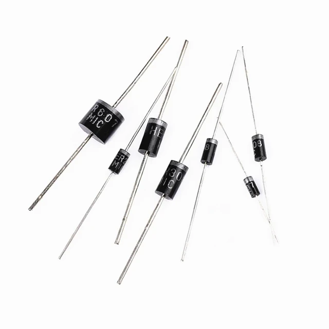
There are several types of diodes, each designed for specific purposes and applications. Here are some common types of diodes:
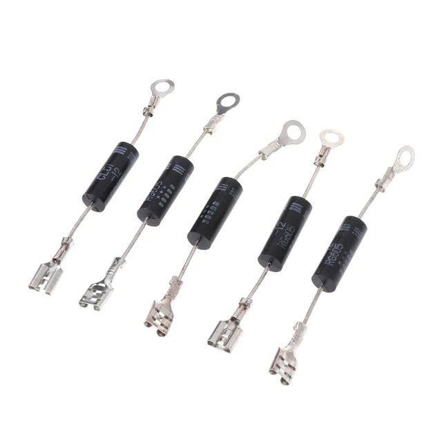
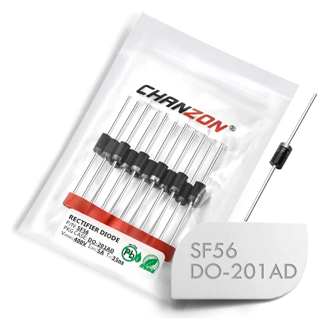
Rectifier Diodes:
Rectifier diodes are widely used in power supply circuits to convert alternating current (AC) into direct current (DC). They allow current to flow in only one direction, blocking the reverse flow of current.
Light Emitting Diodes (LEDs):
LEDs are semiconductor diodes that emit light when a forward voltage is applied. They are commonly used in lighting applications, displays, indicators, and electronic devices.
Zener Diodes:
Zener diodes are specialized diodes designed to operate in reverse breakdown voltage region. They regulate voltage by providing a constant voltage drop when the current flows in the reverse direction. Zener diodes are commonly used in voltage regulation and protection circuits.
Schottky Diodes:
Schottky diodes are characterized by their fast switching speed and low forward voltage drop. They are commonly used in high-frequency applications, rectifier circuits, and digital circuits.
Avalanche Diodes:
Avalanche diodes have a similar principle to Zener diodes, but they have a higher breakdown voltage and are designed to handle higher power levels. They are used in circuits that require voltage clamping and protection against voltage spikes.
Varactor Diodes:
Varactor diodes, also known as varicap diodes or tuning diodes, are designed to act as voltage-controlled capacitors. They are used in radio frequency (RF) tuning circuits and voltage-controlled oscillators.
Laser Diodes:
Laser diodes are semiconductor devices that emit coherent and intense light of a specific wavelength. They are used in applications such as telecommunications, laser pointers, laser printers, and optical storage devices.
These are just a few examples of the many types of diodes available. Each type has specific characteristics and applications tailored to different electronic and electrical functions. Understanding the specific properties of different diodes helps engineers and technicians select the appropriate diode for their circuit design or application requirements.
 Introduction to Testing a Diode with a Multimeter
Testing a diode allows you to verify its forward and reverse bias behavior, ensuring its proper operation within an electronic circuit.
A. Importance of Diode Testing: Diodes need to be checked for functionality to prevent issues such as incorrect current flow, signal distortion, or potential circuit failures.
B. Testing with a Multimeter: Using a multimeter helps measure the voltage drop across the diode and determines if it is functioning as expected.
Necessary Equipment
Before testing a diode with a multimeter, ensure you have the following equipment:
A. Digital Multimeter (DMM): Use a digital multimeter with diode testing capabilities, preferably one with a diode symbol on its selection dial.
B. Diodes for Testing: Collect a few diodes of various types (e.g., silicon, germanium) to compare readings and validate the operation of the multimeter.
Setting the Multimeter for Diode Testing
Configure the multimeter to the appropriate settings for diode testing.
A. Turn on the Multimeter: Ensure the multimeter is turned on and functioning correctly.
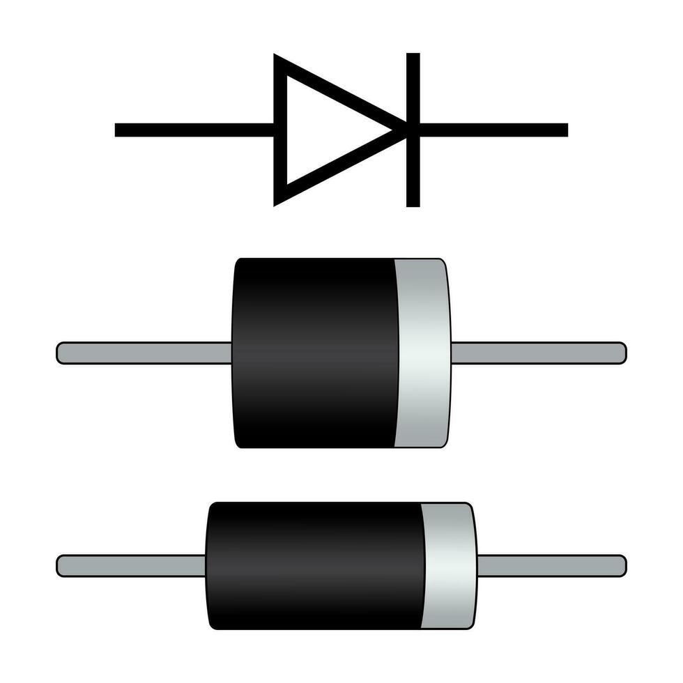
B. Select Diode Test Mode: Rotate the selection dial of the multimeter to the diode testing mode, often indicated by a diode symbol.
 Identifying the Diode’s Polarity
How to test diode with multimeter?
Determine the polarity of the diode before testing.
A. Identify the Cathode and Anode: Refer to the diode’s datasheet or markings to identify its cathode (-) and anode (+) terminals.
B. Connect the Diode: Connect the diode to the multimeter’s test leads, with the anode connected to the red positive (+) lead and the cathode to the black negative (-) lead.
Testing the Diode in Forward Bias
Testing the diode in forward bias confirms its expected functionality.
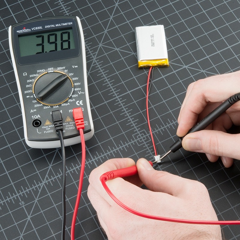
A. Connect the Leads: Connect the multimeter’s test leads to the diode, ensuring the red positive (+) lead is connected to its anode and the black negative (-) lead to its cathode.
B. Read the Voltage: Observe the voltage reading displayed on the multimeter. A typical silicon diode should show a voltage drop of around 0.6 to 0.7 volts, while a germanium diode should display approximately 0.2 volts.
Testing the Diode in Reverse Bias
Testing the diode in reverse bias ensures it blocks current flow appropriately.
A. Reverse the Leads: Swap the connections of the multimeter’s test leads, connecting the red positive (+) lead to the diode’s cathode and the black negative (-) lead to its anode.
B. Observe Display Reading: Check the multimeter’s display for a reading. Ideally, the display should show “OL” (for “open loop”), as the diode should prevent any significant current flow in reverse bias.
Interpreting the Test Results
Interpret the test results based on the observations made during the diode testing.
A. Expected Voltage Drop: If the forward voltage drop falls within the typical range for the diode type, the diode is likely functioning correctly.
B. Reverse Bias Behavior: If the multimeter displays “OL” during reverse bias, this indicates that the diode is blocking current flow adequately.
Testing Different Diode Types
Repeat the testing process with diodes of various types to compare readings and validate the multimeter’s accuracy.
A. Silicon Diode: Test a silicon diode, observing a forward voltage drop of approximately 0.6 to 0.7 volts and an “OL” display in reverse bias.
B. Germanium Diode: Test a germanium diode, noting a forward voltage drop of about 0.2 volts and an “OL” reading in reverse bias.
 Conclusion
How to test diode with multimeter?
Testing a diode with a multimeter is a simple and effective method for ensuring the proper functionality of these essential electronic components. By following the step-by-step guide provided in this article, you can confidently test diodes, identifying potential issues and guaranteeing reliable performance within electronic circuits. Remember to observe the voltage readings during forward bias and the absence of significant current flow in reverse bias. By conducting regular diode testing, you can troubleshoot and prevent potential problems in electronic devices. Mastering the art of diode testing with a multimeter empowers you to maintain and enhance the efficiency and reliability of your electronic circuits.