 Introduction:
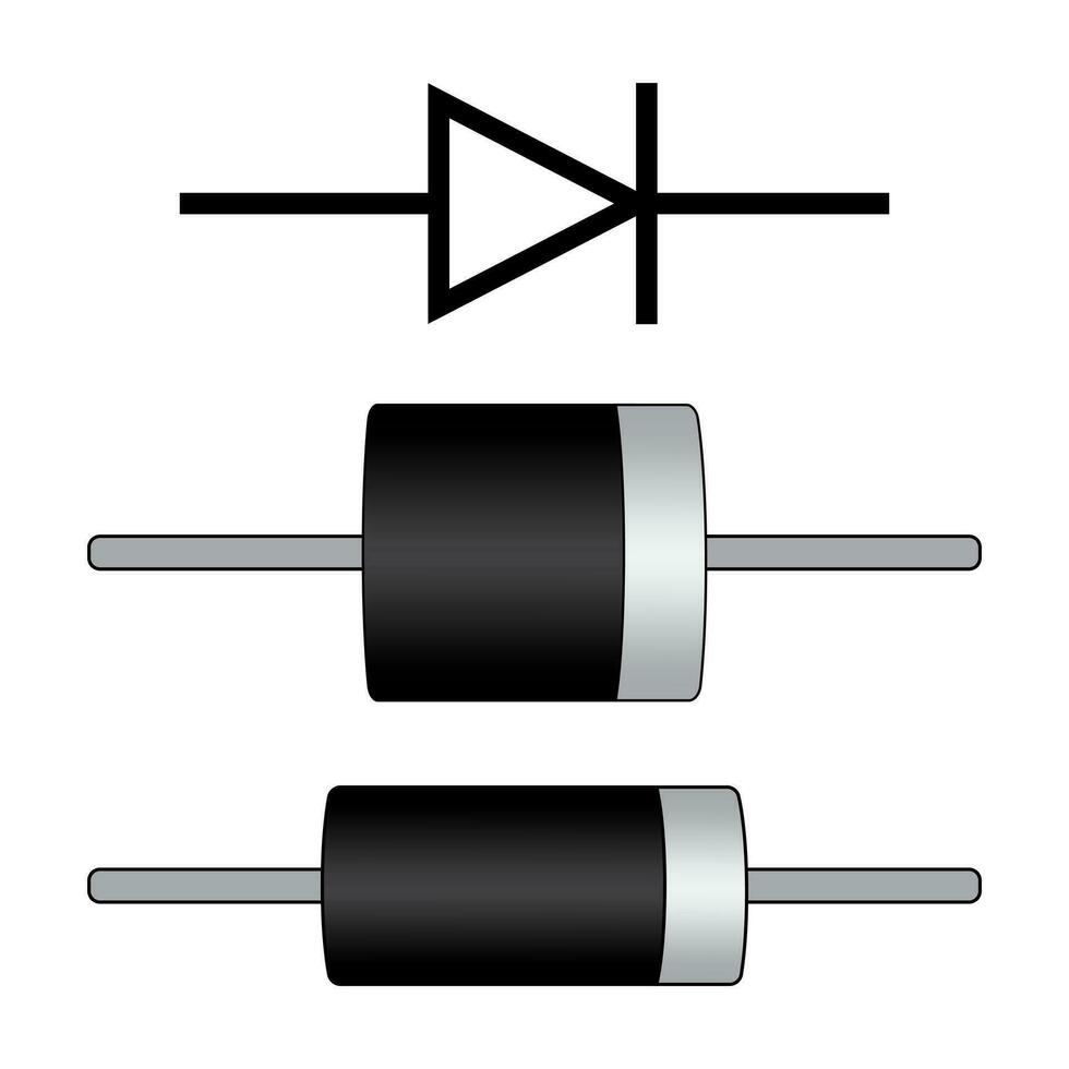
The diode test is an important electrical measurement that helps determine the functionality and health of diodes. Diodes are electronic components that allow current to flow in one direction while blocking it in the opposite direction. In this comprehensive guide, we will explore the purpose and procedure of it. By understanding the significance of this test and how to perform it correctly, you can troubleshoot and ensure the proper functioning of diodes in various electronic circuits.
 Introduction to Diode Test
It is a method of checking the condition and polarity of diodes.
A. Importance of Diodes: Diodes are crucial components in various electrical and electronic circuits, controlling the direction of current flow.
B. Purpose of the Diode Test: It helps identify faulty diodes, verify their polarity, and ensure they meet specified parameters.
Some common types of diodes:
There are several types of diodes, each designed for specific applications and operating characteristics. Here are some common types of diodes:
Rectifier Diode:
Rectifier diodes are the most basic type of diode. They are used to convert alternating current (AC) to direct current (DC) by allowing current flow in only one direction. Rectifier diodes are commonly used in power supplies and electronic circuits that require DC power.
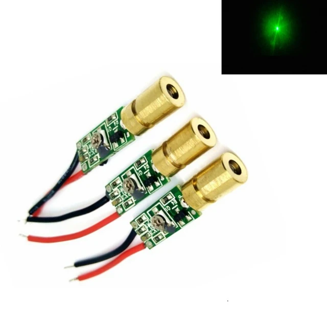
Light-Emitting Diode (LED):
LEDs are diodes that emit light when current flows through them. They are widely used in lighting applications, displays, indicators, and electronic devices. LEDs are energy-efficient and available in a wide range of colors.
Zener Diode:
Zener diodes are designed to operate in reverse-biased mode and maintain a relatively constant voltage across their terminals, even when the reverse voltage exceeds a certain threshold. They are commonly used for voltage regulation, surge protection, and voltage reference applications.
Schottky Diode:
Schottky diodes are characterized by their low forward voltage drop and fast switching speed. They are commonly used in high-frequency applications, rectification circuits, and power supplies. Schottky diodes are ideal for applications where fast switching and low power loss are required.
Varactor Diode:
Varactor diodes, also known as voltage variable capacitors or tuning diodes, are used in electronic circuits for voltage-controlled tuning, modulation, or frequency synthesis. Their capacitance varies with the applied voltage, making them suitable for applications such as voltage-controlled oscillators and frequency mixers.
Avalanche Diode:
Avalanche diodes are designed to operate in reverse breakdown voltage regions to take advantage of the avalanche effect. They are used for applications such as voltage clamping, surge protection, and transient voltage suppression.
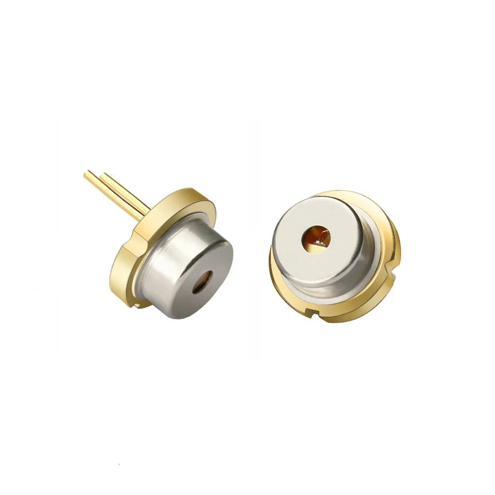
Photodiode:
Photodiodes are light-sensitive diodes that generate a current or voltage when exposed to light. They are widely used in applications such as photovoltaic cells, optical communication systems, light sensors, and optical switches.
These are just a few examples of the various types of diodes available. Each type has specific characteristics, making it suitable for different electronic applications and functions. The selection of the appropriate diode type depends on the requirements of the specific circuit or device being designed.
Purpose of Diodes
Understanding the purpose of diodes provides context for the importance of them.
A. Current Rectification: Diodes allow current to flow in one direction, functioning as a “check valve” in electrical circuits.
B. Voltage Regulation: Diodes can regulate voltage levels in specific applications, such as voltage clamping and stabilization.
Diode Operating Principle
Understanding the basic operating principle of diodes is essential for comprehending the diode test.
A. Forward Bias: In forward bias, diodes conduct current and have a low resistance, allowing electricity to flow uninterrupted.
B. Reverse Bias: In reverse bias, diodes block current flow and have a high resistance, effectively acting as an open circuit.
 Diode Test Setup
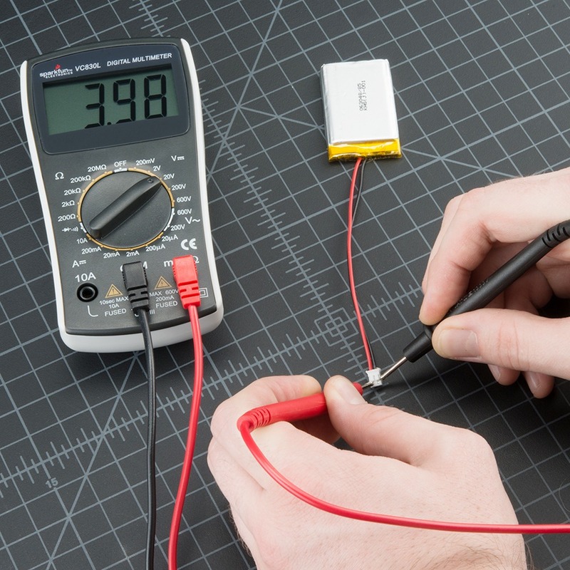
Performing the they requires a few simple steps and equipment.
A. Multimeter Selection: Choose a digital multimeter capable of measuring resistance and diode voltage.
B. Select the Diode Test Mode: Set the multimeter’s mode selector to the diode test or resistance mode.
C. Test Leads Connection: Connect the multimeter’s test leads to the corresponding terminals on the diode.
Performing the Diode Test
Follow these step-by-step instructions to perform the diode test accurately.
A. Identify the Diode Terminals: Locate the anode (positive) and cathode (negative) terminals of the diode.
B. Connect the Test Leads: Attach the red test lead to the anode of the diode and the black test lead to the cathode.
C. Read the Multimeter Display: Observe the multimeter’s display to determine the forward voltage drop or resistance reading.
Diode Test Results Interpretation
Interpreting the them results helps identify the condition and polarity of the diode.
A. Normal Forward Bias Reading: A normal diode test reading displays a forward voltage drop within the specified range (e.g., 0.6V for silicon diodes).
B. Open or Shorted Diode: An open or shorted diode typically reads “OL” or an extremely low resistance, indicating a fault.
C. Reverse Bias Reading: In reverse bias, a functioning diode should display a high resistance or “OL” on the multimeter.
 Diode Test Application and Troubleshooting
The diode test has various applications, including circuit troubleshooting and component verification.
A. Identifying Faulty Diodes: By performing the diode test, faulty or malfunctioning diodes can be identified and replaced.
B. Polarity Verification: The diode test ensures diodes are correctly connected with the proper polarity in electronic circuits.
Precautions and Safety Measures
Taking appropriate precautions during the diode test ensures safety and accurate measurements.
A. Disconnect Power: Always disconnect power from the circuit or device before performing the diode test.
B. Reverse Bias Limitation: Avoid applying reverse bias voltage higher than the diode’s maximum reverse voltage rating to prevent component damage.
 Conclusion
The diode test is a critical measurement technique for verifying the functionality, polarity, and health of diodes. By understanding the purpose and operating principle of diodes, as well as following the step-by-step instructions to perform the diode test correctly, you can troubleshoot circuit issues and ensure the reliability and performance of electronic systems. The diode test’s simplicity and effectiveness make it a valuable tool for electronics enthusiasts, technicians, and engineers. With the ability to perform the diode test, you can confidently assess and maintain the health of diodes in a wide range of applications.