 Introduction:
The Zener diode is a unique type of diode that is primarily used for voltage regulation and protection in electronic circuits. It has a specific symbol that represents its function and characteristics in circuit diagrams. In this comprehensive guide, we will explore the Zener diode symbol, its components, and its significance. By understanding its representation, you can effectively identify and utilize Zener diodes in circuit designs and troubleshooting.
 Introduction to Zener Diodes
Zener diodes are special diodes that can regulate voltage and provide protection against voltage spikes or surges.
A. Voltage Regulation: Zener diodes are specifically designed to maintain a constant voltage across their terminals.
B. Reverse Breakdown: Zener diodes operate in reverse bias mode, allowing current to flow when the voltage across their terminals exceeds a specific threshold known as the breakdown voltage.
Materials:
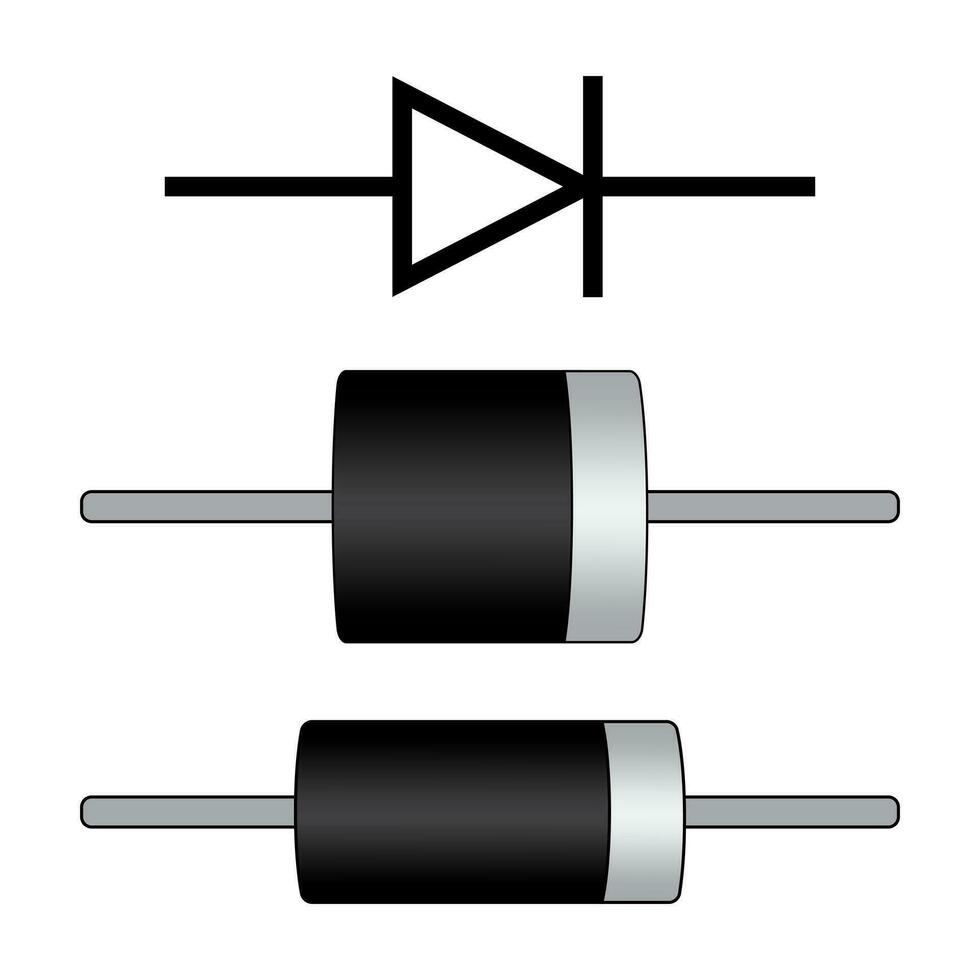
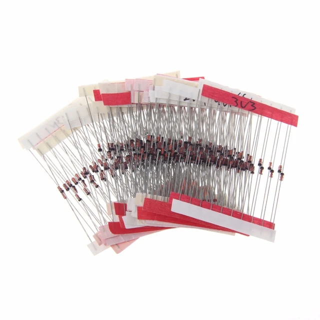
Zener diodes are typically made from semiconductor materials, specifically doped silicon or germanium. These materials are used due to their unique electrical properties that allow them to function as Zener diodes. Let’s look at a brief explanation of each material:
Silicon Zener Diodes:
Silicon-based Zener diodes are the most common type and widely used in various applications. Silicon is a widely available semiconductor material that has good temperature stability and high breakdown voltage characteristics. Silicon Zener diodes can handle higher power levels and exhibit better stability over a wide range of temperatures.
Germanium Zener Diodes:
Germanium-based Zener diodes are less common than silicon but still used in specific applications. Germanium has a lower bandgap compared to silicon, which gives germanium diodes a lower forward voltage drop. However, germanium diodes have lower breakdown voltages and are more sensitive to temperature variations, making them less suitable for high-power applications.
Both silicon and germanium Zener diodes are widely available and manufactured to meet specific breakdown voltage and current requirements. The choice of material depends on the desired electrical characteristics and the specific needs of the application.
 Components of the Zener Diode Symbol
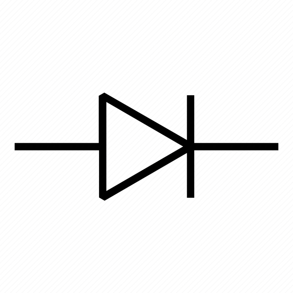
The Zener diode symbol consists of various elements that represent its function and characteristics.
A. Triangle Shape: The Zener diode symbol is depicted by a triangle pointing towards the cathode terminal.
B. Vertical Line: A vertical line extends from the bottom of the triangle, representing the cathode terminal.
C. Diagonal Line: A diagonal line cuts across the triangle, separating the anode and cathode terminals.
Understanding the Zener Diode Symbol
The Zener diode symbol represents its unique properties and functions.
A. Triangle as the P-N Junction: The triangle shape represents the P-N junction, which is the core component of a diode.
B. Reverse Breakdown and Voltage Regulation: The diagonal line in the symbol signifies the reverse breakdown characteristic of Zener diodes, resulting in voltage regulation.
C. Cathode and Anode Terminals: The vertical line indicates the cathode terminal, while the area above the diagonal line represents the anode terminal.
Significance of the Zener Diode Symbol
The Zener diode symbol plays a crucial role in circuit diagrams, enabling easy identification and understanding of Zener diodes in various circuit designs.
A. Circuit Placement: The symbol indicates the correct placement of the Zener diode within the circuit.
B. Voltage Regulation: The symbol signifies the voltage regulation function of Zener diodes, helping designers ensure stable and constant voltage levels.
C. Protection Mechanism: Zener diodes offer protection against voltage spikes or surges, and their symbol allows for easy identification within protective circuits.
Variations in Zener Diode Symbols
While the basic elements of the Zener diode symbol remain the same, there can be slight variations based on regional conventions or specific circuit diagram representations.
A. Arrow Orientation: In some cases, the arrow within the triangle may point in the opposite direction to indicate the flow of current.
B. Additional Labels: Depending on the circuit diagram or designer’s preference, additional labels may be included to provide more information about the Zener diode, such as its breakdown voltage or other specifications.
 Measure the characteristics of a Zener diode:
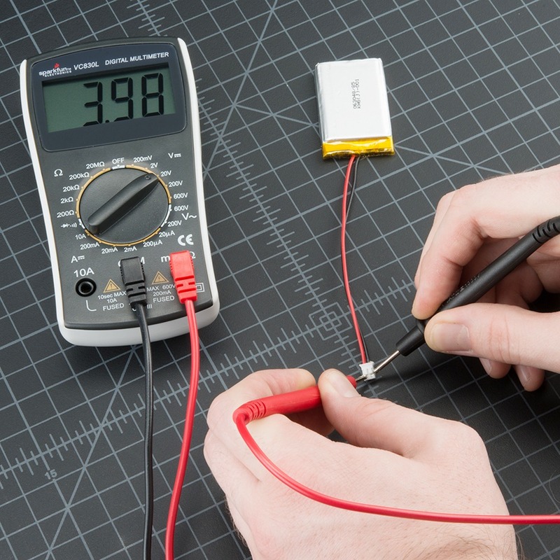
To measure the characteristics of a Zener diode, you can follow these steps:
Turn off the power:
Before starting the measurement, ensure that the circuit or device containing the Zener diode is turned off and disconnected from any power source.
Identify the anode and cathode:
Locate the anode (typically marked with a “+” or a band) and cathode (typically marked with a “-” or no band) terminals of the Zener diode. It is important to connect the diode in the correct orientation for accurate measurement.
Set the multimeter:
Set your multimeter to the diode or Zener diode testing mode. This mode typically uses a small forward voltage (around 0.7V) to test the diode.
Connect the multimeter:
Connect the multimeter’s test leads across the Zener diode, ensuring that the positive lead is connected to the anode and the negative lead to the cathode. The multimeter will display the forward voltage drop across the diode.
Reverse bias test:
To measure the Zener breakdown voltage, connect the multimeter in reverse bias mode. Connect the positive multimeter lead to the cathode and the negative lead to the anode. Gradually increase the voltage while monitoring the multimeter reading. The voltage at which the Zener diode conducts and starts to exhibit the Zener breakdown is the breakdown voltage.
Current measurement:
If necessary, measure the current flowing through the Zener diode using a current measuring device, such as an ammeter. Connect the ammeter in series with the Zener diode to measure the current accurately.
Remember to follow the manufacturer’s guidelines and safety precautions while measuring the Zener diode to avoid damaging the diode or the measuring equipment.
 Conclusion
The Zener diode symbol is an essential element in circuit diagrams, representing the unique properties and functions of Zener diodes. By understanding the triangle shape, vertical and diagonal lines, and the significance of the cathode and anode terminals, you can easily identify Zener diodes and utilize them effectively in voltage regulation and protection circuits. Recognizing the symbol’s variations and additional labels enhances your ability to decipher circuit diagrams accurately. Embrace the significance of the Zener diode symbol and confidently incorporate Zener diodes into your circuit designs and troubleshooting processes.