 Introduction:
Testing a diode is an essential skill for electronics enthusiasts, technicians, and engineers. A diode is a semiconductor device that allows current to flow in one direction, and testing it ensures its proper functioning. In this comprehensive guide, we will explore the step-by-step process of testing a diode using a digital multimeter. By following these simple instructions, you can easily determine whether a diode is functional or needs to be replaced.
 Introduction to Diode Testing
Diode testing verifies the functionality and integrity of the diode, ensuring it operates correctly within an electronic circuit.
A. Importance of Diode Testing: Faulty or damaged diodes can impact circuit performance and lead to malfunctioning electronic devices.
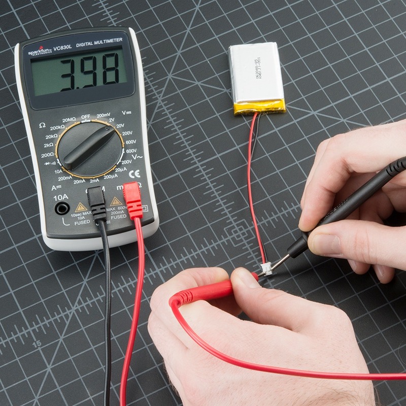
B. Using a Digital Multimeter: A digital multimeter (DMM) is a versatile tool that can be used to test diodes accurately.
 Common types of diodes:
There are several types of diodes, each with its unique characteristics and applications. Here are some common types of diodes:
Rectifier Diode:
Rectifier diodes are primarily used for converting alternating current (AC) to direct current (DC) by allowing current to flow in only one direction. They are commonly used in power supplies and electronic circuits.
Light-Emitting Diode (LED):
LEDs are diodes that emit light when an electric current passes through them. They are widely used in various applications, including lighting, digital displays, indicators, and automotive lighting.
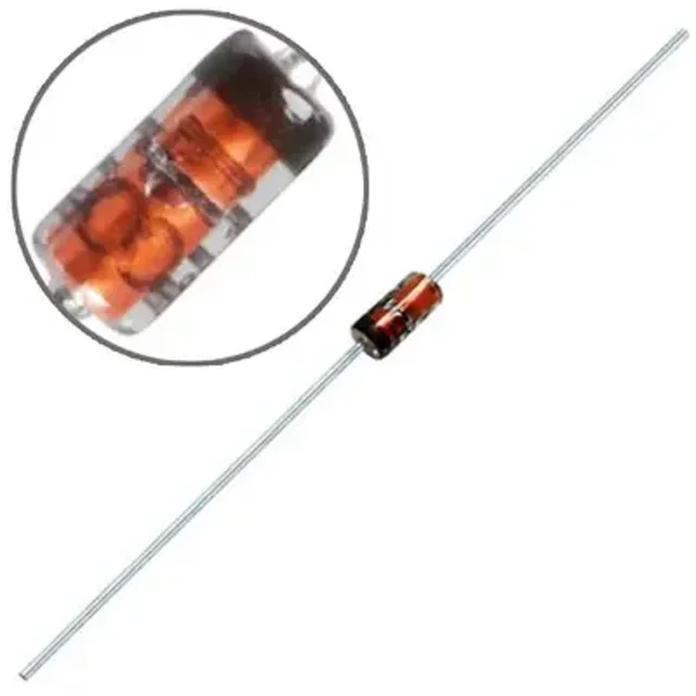
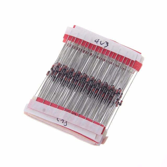
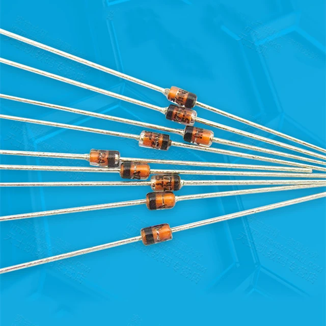
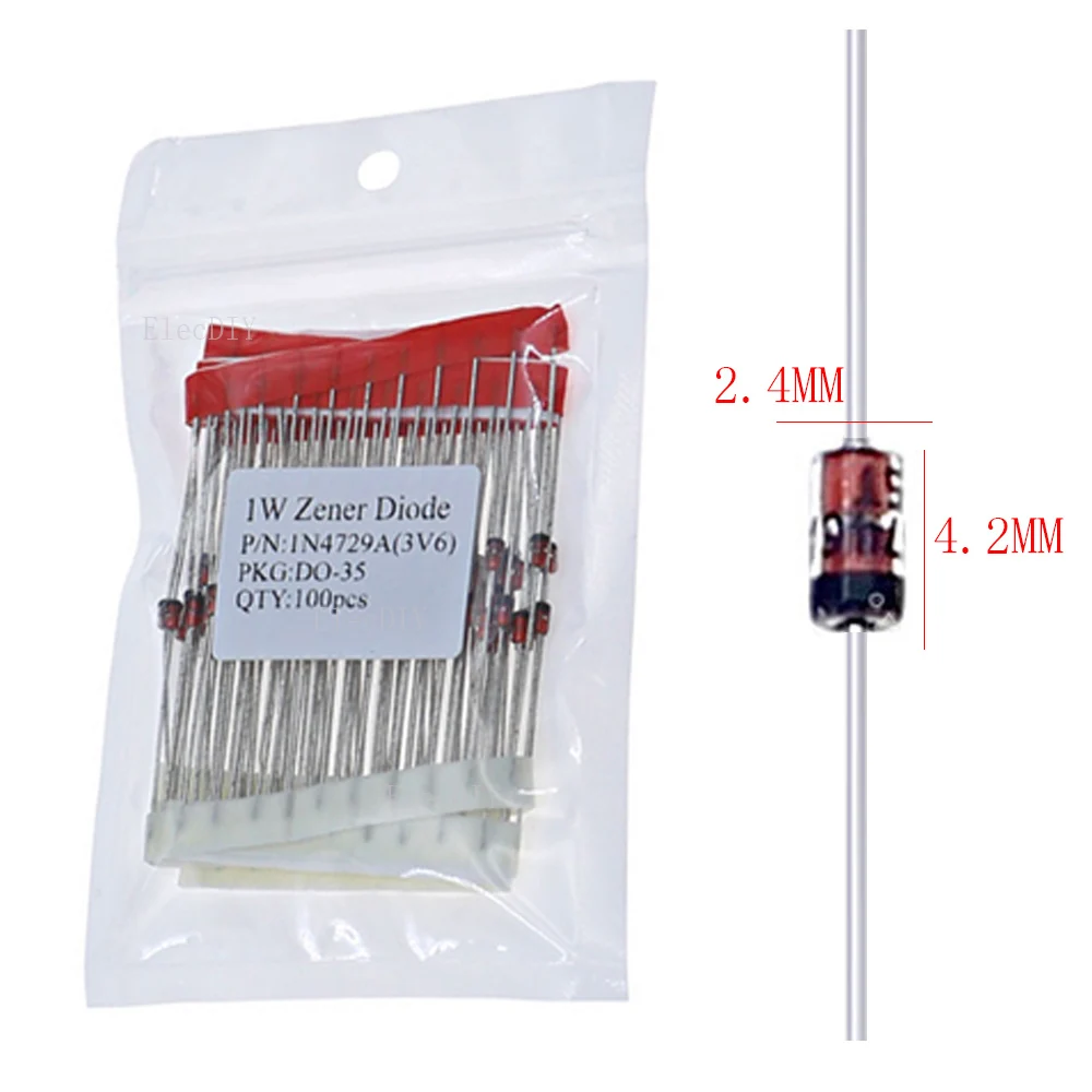
Zener Diode:
Zener diodes are designed to operate in the reverse breakdown region, maintaining a nearly constant voltage across their terminals. They are commonly used in voltage regulation, voltage clamping, and protection circuits.
Schottky Diode:
Schottky diodes, also known as hot-carrier diodes, have a low forward voltage drop and fast switching characteristics. They are often used in high-frequency applications, rectification, and power management circuits.
Tunnel Diode:
Tunnel diodes exhibit a unique negative resistance characteristic, allowing them to function as high-speed switching devices. They find applications in microwave and high-frequency circuits, as well as in oscillators and amplifiers.
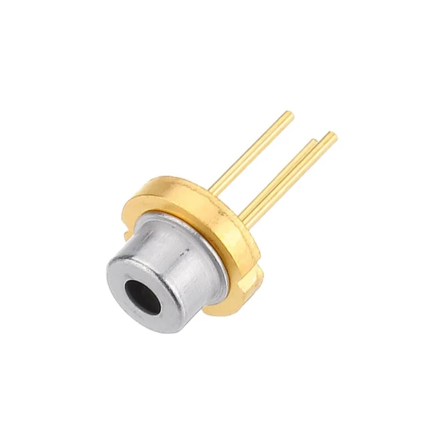
Photodiode:
Photodiodes are sensitive to light and convert light energy into electric current. They are widely used in light sensors, optical communication systems, and imaging devices.
Varactor Diode:
Varactor diodes, also known as voltage-variable capacitors, change their capacitance value according to the applied voltage. They are used for frequency tuning, voltage-controlled oscillators, and in voltage-controlled filters.
These are just a few examples of the different types of diodes available. Each type has specific electrical characteristics that make it suitable for different applications in electronics, telecommunications, lighting, and more.
 Understanding Diode Polarity
Before testing a diode, it is crucial to identify the anode and cathode terminals.
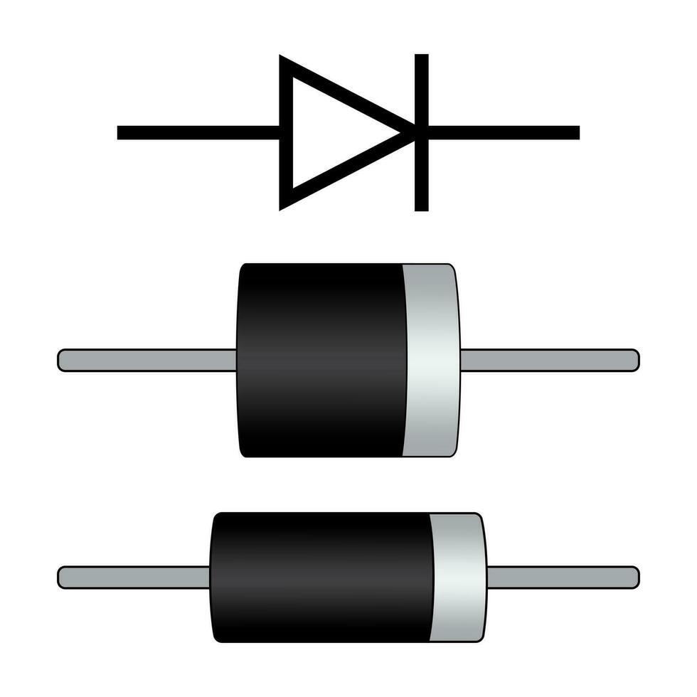
A. Diode Symbols: Familiarize yourself with the diode symbol, representing the anode and cathode terminals.
B. Anode and Cathode Identification: Usually, the cathode terminal is marked by a stripe or line on the diode’s body.
Setting Up the Digital Multimeter
Properly configuring the multimeter ensures accurate diode testing.
A. Selecting the Diode Testing Mode: Switch the multimeter to the diode testing mode, often denoted by a diode symbol.
B. Identifying the Diode Testing Terminals: Locate the diode testing terminals on the multimeter, typically labeled as “+,” “-” or “COM.”
Testing a Diode
Follow these steps to test a diode using a digital multimeter:
A. Turn Off Power: Ensure the circuit is powered off before attempting to test the diode for safety reasons.
B. Diode Placement: Position the diode in the correct orientation, matching the anode and cathode with the corresponding terminals on the multimeter.
C. Measure Forward Bias: Connect the anode of the diode to the positive terminal and the cathode to the negative terminal on the multimeter. Note the voltage reading displayed on the screen.
D. Reverse Bias Measurement: Reverse the diode by connecting the anode to the negative terminal and the cathode to the positive terminal on the multimeter. Again, observe the voltage reading.
Interpreting Diode Test Results
Based on the voltage readings obtained during testing, diodes can be classified as functional or faulty.
A. Forward Bias Test Results: A voltage reading close to zero or a few millivolts indicates the diode is functional.
B. Reverse Bias Test Results: A high voltage reading or an “open” or “OL” message on the multimeter suggests that the diode is working correctly.
C. Diode Failures: If a diode fails the forward bias test (no voltage reading) or the reverse bias test (low voltage reading), it is likely faulty and needs replacement.
Additional Considerations
Consider the following points to ensure accurate diode testing:
A. Multimeter Range: Verify that the multimeter range is set to an appropriate level for accurate voltage readings.
B. Temperature and Environmental Conditions: Extreme temperatures or other environmental factors can affect diode testing results.
Some important points to remember:
When testing a diode, there are a few precautions and considerations to keep in mind. Here are some important points to remember:
Safety:
Ensure that the power to the diode and the circuit it’s connected to is turned off before testing. This protects against electric shock and potential damage to the diode or other components.
Testing Equipment:
Use a multimeter or a dedicated diode tester that is designed for diode testing. Follow the manufacturer’s instructions for proper usage.
Polarity:
Diodes are polarized components, meaning they have a specific direction of current flow. It is essential to identify the diode’s anode (positive terminal) and cathode (negative terminal) before testing. Testing the diode in the correct orientation is crucial for accurate results.
Forward Bias Testing:
Connect the diode to the testing equipment and apply a voltage in the forward bias direction. A working diode should allow current to flow in the forward direction, displaying a low resistance or a forward voltage drop (typically around 0.6-0.7 volts for silicon diodes).
Reverse Bias Testing:
Reverse bias testing checks for the diode’s ability to block current in the reverse direction. Apply voltage in the opposite direction to the diode. A functioning diode should show a very high resistance or no current flow, indicating successful reverse bias behavior.
Interpretation of Results:
Based on the readings obtained during testing, compare them to the specifications provided by the diode’s datasheet or the expected values for the specific type of diode being tested. If the readings deviate significantly from the expected values, it may indicate a faulty or damaged diode.
Temperature:
Diodes can be sensitive to temperature changes, so it’s advisable to perform the testing at room temperature or within the specified temperature range provided by the manufacturer.
By following these precautions and guidelines, you can safely and accurately test a diode to determine its functionality and ensure proper circuit performance.
 Conclusion
Testing a diode using a digital multimeter is a simple yet essential skill for electronics enthusiasts and professionals. By following the step-by-step guide outlined above, you can accurately determine the functionality of a diode in an electronic circuit. Proper identification of diode polarity, correct setup of the digital multimeter, and interpretation of voltage readings are crucial for accurate testing. Remember to observe safety precautions and ensure the circuit is powered off before conducting diode testing. With practice and familiarity, you can confidently test diodes, troubleshoot circuit issues, and maintain efficient electronic systems.